|
Website visitor Scott wrote to request
that I post the article for the Slingsby Type 49 Capstan Glider glider that was published
in the August 1972 edition of American Aircraft Modeler. This version is a rudder-only,
all-balsa sheet model with about a 70" wingspan. I say "about" because there is no size
scale on the plans and the wingspan is not mentioned in the article. The guess is made
by measuring the printed right wing panel length and calculating the scale from the size
of 1/8" ribs. An optional .020 power pod is provided.
Per Wikipedia: "The Slingsby T.49 Capstan is a British two-seat glider of the 1960s built
by Slingsby Sailplanes as a replacement for their earlier Type 42 Eagle. It is a high-winged
monoplane of wooden construction, the last two-seat wooden glider built by Slingsby,
intended for both training and general club flying. Side-by-side seats for the two pilots
are accommodated in an enclosed cockpit with a one-piece perspex canopy. The prototype
T.49A first flew in 1961, and it entered production as the T.49B in 1963. Thirty-four
Capstans were built, one of which was fitted with an auxiliary engine with the designation
T.49C Powered Capstan. "
9/9/2011 Update: Jack Headley's daughter, Lisa, just sent me the
following e-mail.
"Hi Kirk[sic], it was fun to see my father's article (JW Headley in Aircraft
Modeler, August 1972) on your website. I did not even think these old articles were around
and still being read. My son just started getting interested in model aircraft and I
want to try and find his grand dad's articles. I tried a search on your website and found
only this one article. Thanks again for keeping his work alive."
This is part of the reason I post these articles.
Capstan
Light rudder-only glider based on the Slingsby two-seat trainer.
by Jack Headley
|
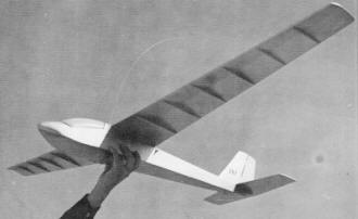 Completed Capstan,
ready to fly
Equipment shown came out of a Testor's ready-to-fly RC Skyhawk. Range is excellent and
magnetic actuator powerful enough for Capstan's big rudder. Small digital could be used,
too. |
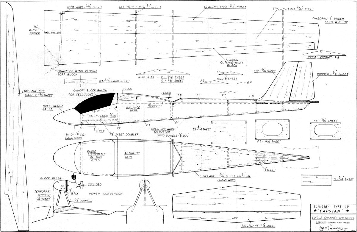
The Slingsby Type 49B Capstan is a simple wood and fabric training glider, with side-by-side
seating, intended for all stages of training and glider club flying. The simplicity of
line was one of the things that attracted us to this model, together with the wide cockpit
area which provides ample space for all the radio gear. Our model is a simplified version
of this design, for single-channel radios, including galloping ghost types.
Also included on the plan is another version of the design, the Type 49C "Powered
Capstan" - a standard Capstan with a 45 hp Nelson engine mounted on a pylon above the
wings. This type first flew in 1968. We used an 020 engine for our model version, and
this unit provides almost scale type performance. If you make the powered version, don't
forget to use fuel proof dope when finishing the model. (The following construction notes
apply to either version.)
Construction
All construction articles seem to assume that the builder will begin building very
logically with one piece, the body or the wings for example, and then work steadily to
finish this piece before beginning the next. This may be their way of doing it, but my
system is to go into a building "frenzy," which the dictionary defines first as "a temporary
madness" (could be!), but later as "compulsive or agitated activity" which is more my
description, and make everything at the same time doing a bit at the wings while the
body is drying, then making the tail while both are drying, etc. No piece ever gets finished
before another until suddenly it's all done. But everyone has their own techniques, and
so the following notes are written assuming each piece is built separately. It's recommended,
however, that you read through to the end before beginning balsa cutting, or you might
find that you've omitted the "flangle-sprocket," which is very, very important, and can't
be put in afterwards.
Construction of the fuselage begins by cutting out two fuselage sides from 1/16" sheet.
Be sure to choose the correct grade of wood for these pieces - medium hard is the most
suitable. It's also important to make the two sides from the same or similar sheets of
wood. Cement onto these sides the 1/8" square framework and the 1/8" sheet doublers at
the nose and wing locations.
While
all this is drying, the various frames can be made. Frames 1,2,3 and 4 are all made from
3/16" sheet, and 5,6,7 and 8 from 1/8" sheet. The fuselage sides are initially joined
by gluing frames F2, F3, and F4 into place, and then gluing the sides together at the
back, followed by the 1/8" square crosspieces between F4 and the back end. Next cement
into place F 1 and the cockpit floor, the latter resting on the 1/8" sheet doublers in
the nose section. This floor provides a flat area for the radio equipment to rest on,
and also gives the nose section the correct curvature. The various gussets for the wing
dowels are cemented in next, as is the 1/8" sheet fin locator.
The bottom surface is next. Note that the forward portion of this is 1/16" ply, and
the aft portion is 1/16" sheet balsa which is cemented into place with the grain crosswise.
The tailplane, fin and rudder are now installed and the radio can be put in temporarily
to check out the push rod clearances before the turtle deck sheeting is completed. After
this checkout, cement into place frames 5 to 8, and then add the 1/16" sheeting, not
forgetting to close off the front end of this with a triangular scrap of 1/16" sheet.
Add the nose block as well as the canopy block, which should be hollowed out as indicated
on the plans.
There are no great feats of construction for the tail assembly. Just select some straight-grained,
flat, not too heavy sheet, cut out the required outlines and then sand all the edges
round. The rudder can be hinged to the fin in your own pet scheme, but remember if you're
using a galloping ghost system to make the hinges as frictionless as possible. The fin
is attached to the fuselage after the tailplane has been glued into place; it is cemented
to the tailplane at the back and located at the front by the notched piece of 1/8" sheet.
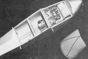
For the radio, the prototype used a double-ended magnetic actuator which was located
in the fuselage under the wing. If you intend to use this type of controller, then reinforce
the floor of this compartment using a scrap piece of1/8" sheet with a piece of 1/16"
ply glued on top. Dope this plywood well, then attach the actuator with servo tape. A
small notch will be required in frame F2 for the wiring. The receiver and batteries are,
as mentioned before, located in the cockpit area and provide almost all the necessary
ballast.
The wings are made of two sections - the forward section is an airfoil shape, and
the rear a constant thickness section. The combination resembles a small chord wing with
an enormous flap. This wing type is simple to build, rugged and easy to repair. Begin
by first shaping the leading edge from a sheet of 3/8" balsa. Carve this to the airfoil
section shown on the plan. Make all the ribs, and pin these down to the plan (note at
this stage all ribs remain the same size). The root rib is cracked slightly to conform
to the fuselage contour. Cement into place the carved leading edge piece. Cut the trailing
edge section from a sheet of 3/32" balsa and cement it into place, making sure that a
good joint is obtained between these two pieces of sheet. The overhanging portions of
the ribs can now be cut away, and the resulting corner trimmed to the shape indicated
on the plans. Make the left wing on the reverse side of the plan in a similar manner
to the above, and then join the two wings using WI, checking also that the correct dihedral
is obtained. Additional strength for the wing joint is provided by the two fairings on
the upper surface. These are carved from block, and then trimmed to the final contour
after completion of the fuselage.
The powered version is built in a similar manner to the glider, and then the power
pod is added. This pod is mainly block balsa with a 1/8" ply plate on which to mount
the engine. Begin by carving the pod from a sandwich of two pieces of block with an 1/8"
sheet core temporarily pinned together. When the correct shape is obtained, remove the
1/8" sheet core and replace it with the 1/8" sheet alignment piece. Glue this lightly
in place to the wing in the correct location. Then from underneath the wing, drill the
holes for the mounting dowels all the way through the wing and into the pod. This operation
has to be done very carefully with the aid of a long 1/8" drill. As each hole is drilled,
insert a temporary piece of dowel to provide additional stiffness. Once all the holes
have been drilled, remove the pod and replace the original core piece into the pod. This
complete assembly can now be cemented together, the engine mounting plate added, and
then in-stalled on the model. Before the glue is dry, make certain that the pod is lined
up correctly. Use a fuel proof finish for this version.
Flying
We could probably go on and on about flying the model, but if you're like me you don't
want to read about flying-flying is something you do (or at least the model does). So
we'll give a few basic suggestions, and then the rest is up to you. First balance the
model at the CG shown on the plans, and recheck to see that no warps have crept into
the model. Try some small glides to determine if this CG is the correct one for the day.
If the model stalls, add more nose weight (and vice-versa). If it won't fly upwind, also
add more nose weight. The only additional step is to establish that you've got enough
control in both directions, and then you're on your own. So happy flying-and soft landings.
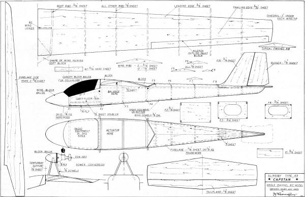 Capstan Plans<click
for larger version>
Notice:
The AMA Plans Service offers a
full-size version of many of the plans show here at a very reasonable cost. They
will scale the plans any size for you. It is always best to buy printed plans because
my scanner versions often have distortions that can cause parts to fit poorly. Purchasing
plans also help to support the operation of the
Academy of Model Aeronautics - the #1
advocate for model aviation throughout the world. If the AMA no longer has this
plan on file, I will be glad to send you my higher resolution version.
Try my Scale Calculator for
Model Airplane Plans.
Posted April 7, 2011
|