|
The
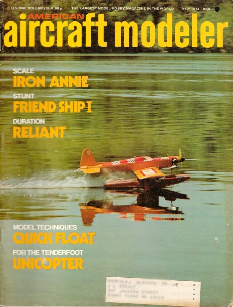
May 1973 edition of American Aircraft Modeler is one of the first
I ever received after joining the AMA. I read and re-read every
page (no Internet edition back then). This Frantique model is one
I desperately wanted to build, but alas, I was a poor newspaper
delivery boy at the time, so the project would have to wait for
the day that time and money was more plentiful. I'm still waiting...
The classic lines of the Frantique remind me of a poor man's Proctor
Antic... sort of. Someday... Baron Von Draftybottom's
latest antique Frantique I
 The
first consideration of an airplane is to fly a model airplane should
do this in spite of all the interference caused by the loose nut
holding the control sticks. The
first consideration of an airplane is to fly a model airplane should
do this in spite of all the interference caused by the loose nut
holding the control sticks. By J. Harmon

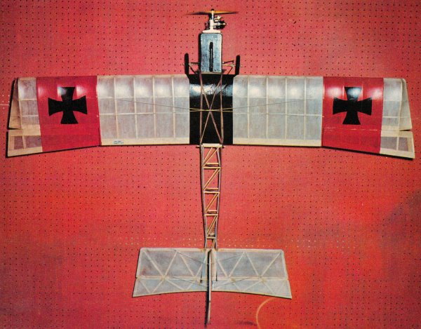
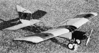
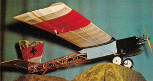
Would you believe this model was inspired by an AAM Tenderfoot
model contest of many years ago? With lots of wing and plenty
of drag, Frantique is a delightful flying plane-slow and gentle.
The nearly symmetrical wing does allow stunting around the field
on a Sunday afternoon.
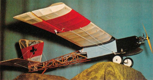
"Frantique" can hold her own when it comes to plowing the "North
Forty" or flying over it. For the beginner who must go out for the
first time by himself or for the sport flier who just wants something
different, Frantique will help.By following a few simple
changes you can fly her as slow or as hot as you like. Version No.1
powered with a 19 to 23 provides moderate flight speeds for the
beginner or for just relaxing. Version No. 2 with a 29 or 35 will
make her walk. Version No.3 is for 40s and up.
If you have the courage to follow into the new world of building
with the new "stick and twig" method of construc-tion and forget
your old-fashioned plastics, styro and other stuff, get some Titebond
and epoxy and let's go. The following are special construction
techniques to be applied with building the particular version you
choose. Version No.1: Build light! Fuselage - make longerons
from spruce as well as bracing from rear landing gear mount forward;
the remainder medium hard balsa, all 3/16 sq. Use 1/16 hard balsa
for covering sides. Wings - use spruce for main spar with 1/8 balsa
web vertical grain from rib 2 to rib 4, 1/16 from rib 4 to rib 7.
All ribs but 1,2 and 11 are made from medium hard 1/16. Rear spars
are medium hard balsa. Version No.2: Fuselage - build entire
fuselage from 3/16 sq. spruce. Use 1/16 ply for sides. Wings - main
spar from spruce laminated as shown. Use 1/4 balsa web from rib
1 to rib 4; from rib 4 to rib 9 use 1/8, and from 9 to 11 use 1/16.
Rear spar is laminated balsa with 1/16 web added from rib 2 to rib
7. Version No.3: Fuselage - increase all wood dimensions
to 1/4. Use spruce for longerons and forward bracing back to rear
landing gear mounting. the remainder using hard balsa. Sides are
covered inside and out with 1/16 ply. Use an extra F-2, and add
an extra layer of 1/16 ply to bottom of fuselage, also Increasing
bottom balsa to 3/16. Landing gear - increase to 5/32 wire as well
as increasing the length one inch to clear for larger props. Wings
- triple laminate of spruce on main spar as shown. Use 1/4 vertical
web from rib 1 to rib 6; from rib 6 to rib 9 use 1/8, and from 9
to 11 use 1/16. Laminate rear spar from balsa as shown and web with
1/8 from rib 1 to rib 7, and with 1/16 from 7 to 11. Increase dihedral
gussets to 3/32 ply. Tail surfaces - change leading edge of stab
by adding an extra spruce spar and adding one to the elevator on
front, position these behind the existing balsa ones. Repeat this
on the vertical fin, front and rear, also to front of rudder.
Using these special references you may begin construction.
If you don't, you're in trouble. Epoxy firewall pieces as
required, clamp and let cure. Begin fuselage by pinning down longerons.
At this time either splice or rip your own, the only splice having
to be made on the bottom. The best place to put it is an inch or
so behind the rear landing gear mount. Next install the
saddles for the wing and stab, then cut and glue in the verticals;
finish by trimming and securing the diagonal members (make all joints
fit as well as possible). After thoroughly dry, build the other
side. To get an identical side build one on top of the other. Install
the rear gussets on the inside of the framework, as well as the
inside sheeting for the No. 3 version. Assemble the forward section
of the fuselage as a box, just be sure all alignment is true; epoxy
firewall F-3 and F-4 in place and let set. Next pull sides
together and cut and install cross members in position. When this
has set, fit the diagonals in the vertical frames and on the top
and bottom. Finish by sheeting the sides and bottom. If
you don't like dowels you can get fancy with the nylon bolts. Make
up the tail skid from hardwood, and insert a wire for hard runways
on the lower front and bottom. Assemble with epoxy. Beam type mounts
from Midwest were used on the original and are highly recommended
as they are very versatile and trouble-free. The mounts from Tatone
or Chopp or similar mounts may also be used. Do not install any
radio equipment or mountings at this time. If you want a little
something extra, you can get fancy with the nose and hatch sections.
I threw in a few lines to give some Idea as to what could be done
with a little extra effort.
If
you are still ambitious, put some false ribs in the wings between
the leading edge and the main spar. If not, proceed by the plans.
First laminate the spars if required, letting them dry while you
notch out the ribs accordingly. The wing panels may be built
on a flat surface as the lower rear of the airfoil is flat. Begin
by laying the spars and trailing edge in place. Set ribs 3 to 11,
set leading edge, align carefully and glue. Measure for the vertical
webbing as required, cut and glue it in place. Add top spars, trailing
edge and aileron crank mounts, the angle at which this mounts will
have to be decided by what length horns to be used. Simply layout
the length of your horn on the plans and plot the pushrod line 1/8
lower than the sheeting over the rear spar. The reason for this
is everyone will use a different amount of throw causing too much
variation. After building both panels decide what dihedral
angle you want to use. If you are like me it will have to have three
inches on each wing. If not, use as little as you like. Then cut
the dihedral gussets long enough to extend an 1/8 or so past ribs
2 and join wing panels. After these have set, install rib pieces
1 and 2, after determining servo location and mounting sheet center
section. Now lay front and rear lower sheet-ing for the ailerons,
set ribs in position back 1/8 from front edge, trim angle on bottom
of aileron spar and glue. Add horn ply mount, bevel front and taper
rear of tip piece and glue. Add top sheet after beveling top spar;
when dry remove and bevel spar to tips, and tip sheeting. Next set
ailerons in wing at neutral position. Line up and install wingtips,
gussets and Sheeting. Use 1/16 to cap entire wing at ribs, spars
and edges of the tips. Install servo and control linkage. If you
feel like it web TE for No.3. The tail surfaces should require
no explanation. Just re-member to add the extra prices for the hot
version-this would not hurt if the rest of you like sustained dives
with hot pullouts. Be sure to get a good joint on the rudder mounting.
The ply horn mounts should be inserted. The landing gear
shown Is tough and does a good job of keeping the ground away. Constructing
it is a little tough too, so practice on some old coat hangers to
get the proper shape. A good pair of Vise Grips is about the best
for this plus some muscle. Slip on a length of tubing for the front
then solder the axle retainers, slip on some more neoprene, one
piece on each side this time, and then join gear at back with a
length of 1/8 10 brass tube and solder. Make axle using wire and
two lengths of this same tubing and eyelets as shown, leaving 1/4"
of tubing on the ends open so you can drill for wheel retainers.
Cover tail surfaces and install after doping rear of fuselage.
Hang engine on the nose and figure balance point with equipment
installed, make up servo mountings and other such odds and ends.
Proceed to finish covering with your favorite white fabric and clear
dope all but the rear fuselage. The original version flying
with an OS Max 19 mounted to the right, with a Heathkit GO 19 weighed
in at about 72 ounces - it flies almost like a powered glider. No
right thrust was found to be necessary. None is shown in the plans
purposely as this can only be determined by the combinations used
and is easily obtained by various methods on the mounts suggested
as needed. There is a small amount of down thrust built in for the
airfoil shown. Flying Go to the nearest flying
field, fuel up, turn equipment on, turn engine on, turn plane loose
and turn yourself on. The "Frantique I"likes to fly as much as you
do. If you get the time take a picture or two and send one
to the old Baron along with a few choice kind words. Send to B.V.D.
at 711 S. Dewey, Sherman, Texas 75090, may all your crackups be
less than straight in.

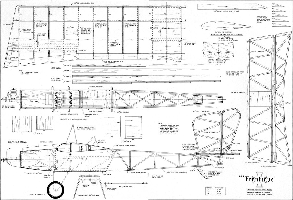
Frantique I Plans
<click for larger
version>
Notice:
The AMA Plans Service offers a
full-size version of many of the plans show here at a very reasonable cost. They
will scale the plans any size for you. It is always best to buy printed plans because
my scanner versions often have distortions that can cause parts to fit poorly. Purchasing
plans also help to support the operation of the
Academy of Model Aeronautics - the #1
advocate for model aviation throughout the world. If the AMA no longer has this
plan on file, I will be glad to send you my higher resolution version.
Try my Scale Calculator for
Model Airplane Plans.
Posted October 22, 2011
|