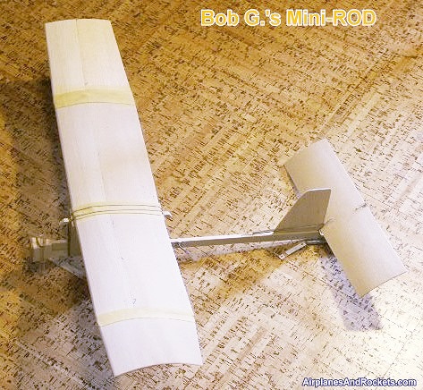
Mini−ROD, by Bob G.
Website visitor Bob G. wrote to request help with identifying a Cox .020-powered
free flight model that he remembered seeing in an old edition of American Aircraft
Modeler modeler magazine. He couldn't recall the name for sure, but gave a
good enough description and a guess at the approximate timeframe that I was able
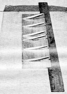
to find it for him - the "Mini−ROD." His completed Mini−ROD is shown to the left.
The finish has not yet been applied. You can see where the wing panels are joined
temporarily with masking tape. The horizontal stabilizer is in its dethermalizer
position. Wing and stabilizers are sheet balsa with airfoil-forming ribs underneath.
A Cox .020 engine will power the Mini−Rod. Bob is planning on building a lot of
the Tenderfoot series of models that appeared monthly back in the era. Note: Bob
is also building a "Chipper II" free
flight model.
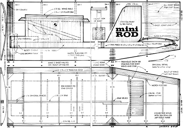
Mini−Rod
 by Bob Stalick by Bob StalickA size free−flight (.020) that
resembles today's big-brother competition designs. Performs like them, too!
It's a sunny afternoon with a slight breeze, You unpack the Mini−Rod, measure the
fuel into the tank, connect the batteries, flip the engine to life, light the dethermalizer
fuse, and launch it into the wind. When the engine stops 15 seconds later, your
model is a bright-colored speck in the sky silhouetted against the white clouds.
Then the fuse burns through the dethermalizer rubber band, the stabilizer trailing
edge pops up, and the Mini−Rod descends slowly into the grass. If this picture stirs
your imagination, you can quickly build a good model from the plans on the next
two pages. Begin on Friday and fly it Sunday.
Mini−Rod is the ideal design for the new AMA-HIAA-Navy youth program as the time−target
free−flight model. This design was arranged so that you can make your first model
from the magazine plan. Mini−Rod is inexpensive, costing less than $1.50 for materials
(less engine). It can be built in two forms. Choose the one you like better. It's
rugged in all-balsa form, but it performs better with the built-up wing.
Mini−Rod has been flown with a number of engines from the .010 Tee Dee to a tired
old .045 Baby Spitfire. It seems happiest with the .020 Cox Pee Wee or Tee Dee.
One Mini−Rod was modified for Jetex 150 power!
The plans are straightforward, but before beginning to work, obtain all the supplies
in the Bill of Materials. Here are a couple of hints for selecting the right kind
of balsa wood to do the best job. C−grain balsa - some call it quarter−grain - has
a strange mottled or freckled appearance with shiny spots. You will generally find
that the lightest and stiffest and strongest wood has this grain. Pick it for wing
spars, ribs, leading and trailing edges. Use it where flat sheets are needed as
it doesn't bend over curves easily. A−grain balsa is identified by the grain streaks
running side−by−side the length of a sheet. It fits over curves - like airfoils
- and rolls into tubes nicely (and especially when wet). So look over the wood rack.
Choose first for strength and then for lightness. Later on, you can shoot for light
weight and compromise on strength.
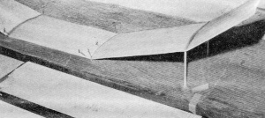
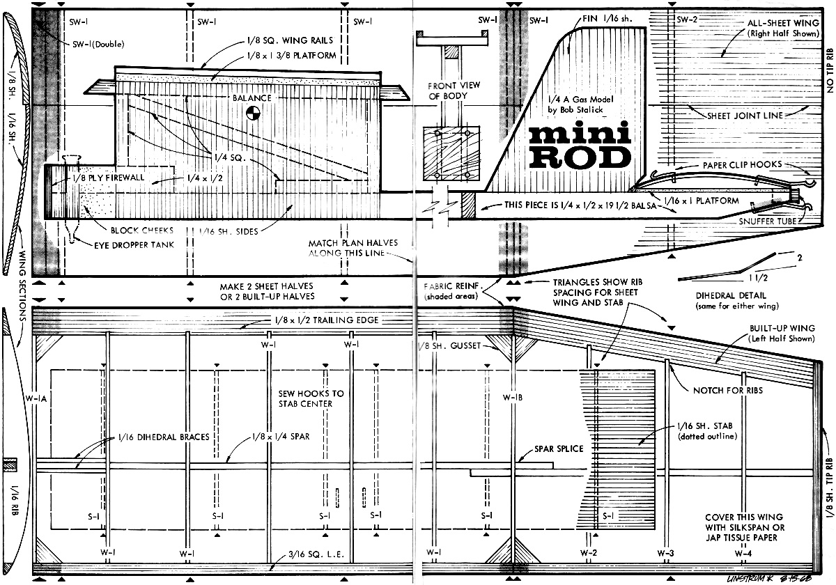
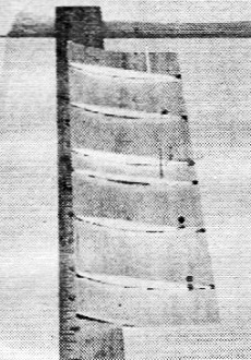
Polyhedral wing - one with "double" dihedral - requires putting
dihedral in tip first, then center section. Sheeted wing shown here.
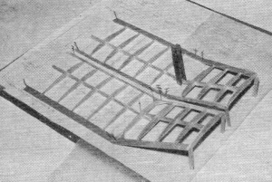
Here's how to put in that dihedral when you make the built-up
wing. Prop up the tips the required amount with wood scraps.
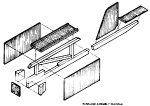
How the fuselage and wing mount go together. Text tells how to
assemble the mount flat on the bench. It's simple and really tough.
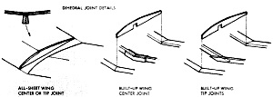
Compare these details with pictures on opposite page to help
with construction of wing dihedral joints. Work slowly for accuracy.
This is how you glue in the ribs on the underside of the sheet-balsa
stabilizer.
Use a ruler or similar object to bend the sheet as necessary
for this two-step operation.
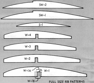
Mini−Rod Rib patterns
Now that you have chosen the materials and readied tools, pick a nice straight and
flat work surface to pin your plans on. Cover plans with waxed paper, then before
you cut anything, read the plans very carefully. Notice that there are two different
types of wings shown. One is sheet balsa, the other is built-up and tissue-covered.
Be careful, don't try to build one wing panel of all balsa, the other with ribs
and spars. Even though Mini−Rod would probably fly with this arrangement, it would
be tough to trim out. For speed and ease of construction, build the balsa sheet
wing first.
Construction:
1) Build the sheet wing by gluing a 30" long 1/8 x 2 sheet of balsa to a similar
length of 1/16 x 3. Be certain that they are glued evenly and securely. I recommend
Sig−Bond or similar adhesive. Cut the tapered tip to shape as indicated on the plans,
and mark all the rib locations directly on the underside of the wing. This is a
good time to sand the topside of the wing to get a good smooth surface joint. Preglue
all the ribs and the sheet where the ribs join. Glue in all ribs, except at the
dihedral joint, starting at the trailing edge on the (on the 1/16 sheet). Allow
this to dry thoroughly. Before gluing the ribs to the leading edge sheeting, dampen
the topside with water to allow the balsa to flex more easily, then pin the ribs
to the 1/8 sheet and glue securely. After this assembly has completely dried, cut
the wing at the dihedral and polyhedral joints where indicated, then with a large
sanding block, sand the ends where the panels join so that they fit when the angle
is glued in. Preglue and allow to dry. Glue the tip panels to the main panels, blocking
them up as indicated. After they have dried thoroughly, join the two wing halves
in a manner similar to that used on the tips.
Add the remaining ribs at the dihedral joints. After everything has dried, reglue
all ribs flush at the bottom of the wing. Add optional cloth reinforcement at the
dihedral joints. The stab is constructed in a similar fashion, with the exception
of the addition of the hold-down hooks glued and sewn as indicated on the plans.
2) Construct the pylon next. Cut sheet size indicated and splice edge-to-edge
the two pieces used to form each side. Mark the location and size of the 1/4 balsa
strip pylon braces and glue into place. Glue on the other pylon side to complete
the structure. Don't glue the pylon to the fuselage yet.
3) Fuselage: The fuselage is simply a piece of 1/4 x 1/2 balsa cut to length
and tapered at the rear as indicated. Notice that the front has an additional piece
of 1/4 x 1/2 balsa glued to the top. Add the 1/8 x 1 x 1 plywood firewall, after
you have fitted your engine, drilled mounting holes and glued the blind nuts into
place. Add the balsa filler blocks to the sides of the fuselage behind the firewall.
Sand a groove into the left side block so an eyedropper fuel tank can be installed.
Right here, a note would be in order to explain how the eyedropper installation
works. You will need to drill a 1/8 to 3/16 hole in the fuel tank of the Pee Wee
(make sure you clean out the metal filings from the tank), attach a length of small
diameter fuel line to the fuel nipple on the needle valve in the Pee Wee tank. Attach
the other end to the eyedropper. You can, in this simple installation, visually
check the amount of fuel remaining and have a simple and effective fuel timer. Fix
the eyedropper to the fuselage by looping a rubber band around the fuselage and
fastening it on each end of the dropper.
Of course you can just estimate the amount of fuel remaining in the Pee Wee tank
and hope that the model doesn't get too high on what you think you've got left -
this is what I did on the first flight of the model in the pictures. Eight minutes
later - no! I didn't light the D.T. (dethermalizer) fuse - it came down, thanks
to cool air, at a good hiking distance downwind.
Glue the rudder onto the fuselage as indicated on the plans, notice the cutout
at the trailing edge. This serves as a stop for the pop-up action of the stab when
dethermalized. Glue on the stab platform.
4) After all component parts are completed, trim with colored tissue and give
the whole structure three coats of clear dope. Install the engine, prop, stab. Fasten
the wing to the pylon with a couple of rubber bands and you are ready for test gliding.
5) Test gliding and flying: Pin or tape the into position and test glide. Move
the forward or back until a good glide, no diving or stalling tendencies, is evident,
then glue pylon into place on the fuselage. It may be necessary to raise the front
of the pylon somewhat if your model is nose-heavy, or to raise the back of the pylon
somewhat if your model is tail-heavy. Try to keep the balance point as indicated
on the as close as possible.
You are now ready for powered flight. As most pylon models, this one has a normal
right power pattern. The model should launched at a 45-degree angle into the wind
and should climb in loose right spirals until the engine cuts, then it should drift
into a tight glide pattern.
Additional glide turn can be achieved by packing the stab platform so that the
right when viewed from the rear, is higher than the right tip. If the model tends
to loop, a small amount of down-thrust (engine tilted down) by inserting washers
behind the two top bolts between the tank mount and the firewall.
After you have had a few successful may wish to build the optional built-up wind
as shown on the plans. This wing is identical in size and shape to the balsa wing,
but it has the additional advantage of a more efficient airfoil and lighter weight.
Transfer the wing rib shapes onto plywood or stiff cardboard and using these as
guides, cut out the indicated number of ribs. Cut the leading and trailing edges
to shape and pin into place. Lay the spar onto the plan and glue in the ribs where
indicated, after you have notched the trailing edges to receive the wing ribs. Additional
details on this type of wing construction can be found in the Jan. '68 issue of
A.A.M., in the article "Get Into Free Flight."
This built-up wing can be substituted for the all-balsa wing, although some changes
will be necessary in the wing angle due to the increased lift of this wing.
Some suggestions: Build the model with the sheet wing first, then, for a surprising
improvement in performance, build the built-up wing.
Always put your name, address, phone number and AMA number on your model. Build
your model as lightly as possible for better performance. The model in the article
weighed 2−3/4 ozs., ready-to-fly in the all-balsa form, and just under 2−1/2 ozs.
in its built-up-wing version.
Always use a fuse to dethermalize your model, even on test flights, as even models
of this type can be lifted high into the sky with a little bit of thermal assistance.
Good luck and many happy flights with your Mini−Rod. Let us know how it flew
for you.
<click for larger version>
Materials List
2 - 1/16 X 3 X 36" balsa sheets for stab, fin, wing ribs and sheeting and pylon
sides
1 - 1/8 X 3 x 36" balsa sheet for wing leading edge and ribs
1 - 1/4 sq. x 36" balsa strip for pylon frame and wing hold-down
1 - 1/4 x 1/2 x 36" balsa strip for fuselage
1 - 1 x 1" pc. of 1/8" thick plywood (In addition, if you plan to make the built-up
wing version, the following wood will be needed.)
1 - 1/8 x 1/4 x 36" balsa strip for wing spar
1 - 1/8 x 1/2 x 36" balsa trailing edge for wing
1 - 3/16 sq. x 36" balsa strip for wing leading edge
4 - 2-56 blind mounting nuts for engine mount
4 - 2-56 x 3/8 or 1/2" mounting bolts 3 - paper clips for misc. hooks
1 - eye-dropper
1 - sheet Silkspan or Jap tissue
Miscellaneous: gauze or other joint-reinforcing fabric; glue; pins; dope and
brushes for finishing.
Notice:
The AMA Plans Service offers a
full-size version of many of the plans show here at a very reasonable cost. They
will scale the plans any size for you. It is always best to buy printed plans because
my scanner versions often have distortions that can cause parts to fit poorly. Purchasing
plans also help to support the operation of the
Academy of Model Aeronautics - the #1
advocate for model aviation throughout the world. If the AMA no longer has this
plan on file, I will be glad to send you my higher resolution version.
Try my Scale Calculator for
Model Airplane Plans.
Posted June 24, 2023
(updated from original post
on 1/10/2012)
|