|
Website visitor Guy wrote to
request that I posted the article for the Supersweep hand-launched glider (HLG)
that appeared in the September 1974 edition of American Aircraft Modeler
magazine. It's good to know that there are still folks pursuing this simplest form
of model airplane building and flying - although there is nothing simple about building
and flying a contest-grade model. Another person, Ward B., wrote later to request
posting of the follow-up
Supersweep 22
article in the October 1974 edition of American Aircraft Modeler.
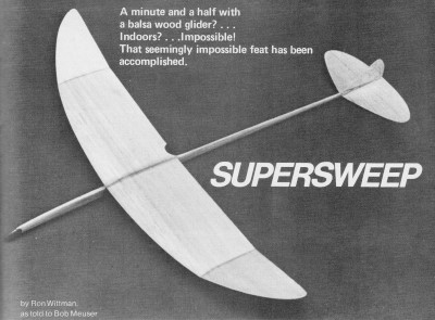
Supersweep Indoor Hand-Launched Glider

The Supersweep 22 has all the lines of a winner. The looks are
deceptively simple, though, as a quick reading of the construction sequence reveals.
By Ron Wittman, as told to Bob Meuser
On February 18, 1973, flying in the old Marine dirigible hanger at Santa Ana,
Ron Wittman made flights of 90.0 sec. and 88.7 sec.-the best two flights in the
series of nine - to establish an official AMA National Record for Indoor Hand-Launched
Gliders, Category III (unlimited ceiling height).
A couple of lucky flights perhaps, made under ideal conditions? Hardly! Rather,
during a year of intensive effort (backed by nearly two decades of previous glider
experience) Ron inched his way toward the record with a series of increasingly successful
designs. Ron made 90 sec. twice, dozens of flights over 85 sec., and only rarely
a flight under 80 sec. And the conditions? The worst imaginable! If the launching
was the slightest bit off, a collision with a parked helicopter was inevitable.
At the 1973 NATS, flying a light straight-dihedral version of the SS22, Bucky
Servaites won the IHLG event in Open Class. And while we were polishing up this
story, Ron's 11-year-old son, Steve, who looks scarcely big enough to carry a 22"
glider, let alone throw one, established a Junior National Record with a two-flight
total of 127.2 sec. That should permanently lay to rest the myth that small people
should fly small gliders.
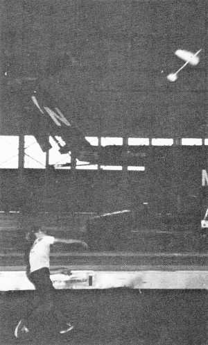
Steve Wittman, the author's 11-year-old protégé, set a Junior
National IHLG Record with the Supersweep. He sure showed dad that record-setting
can be a family affair.
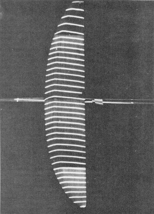
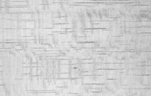
This eerie looking photo is an illumination of the wing with
"sheets" of light to show the airfoil section. The depth is exaggerated, especially
on the ,right wingtip. One can clearly see the tip wash-out, as well as the wash-in
on the left panel.
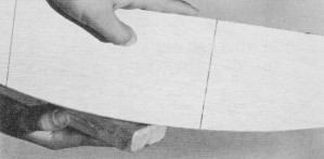
C-grain or quarter-sawed balsa, as shown here, is very resistant
to bending across the width of the sheet. Since it resists warps, it is essential
for true tail surfaces.
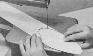
All parts should be jig-sawed to outline, or cut with a sharp
single-edged razor blade.
Final shaping to outline is done with coarse garnet paper.
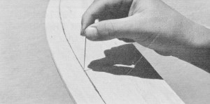
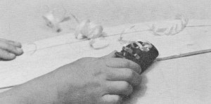
The high point of the wing is marked with pin holes in the partially
shaped wing. The holes remain visible as the sanding progresses.
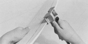
A handy gadget for marking the leading edge is a cabinet maker's
gauge. Accurate marking is essential.
A razor plane saves time, but can cause problems if not properly
used. Note that the cutting edge is angled 45° to the direction of the stroke.
Ron's record was set with the SS22. However, he has actually surpassed his record
by a half second using a 24" span version. While the difference in flight times
is not significant, Ron feels that the Supersweep 24 has more potential than the
SS22, and is currently flying only the 24. The plans are basically those for the
22, but the minor modifications required to stretch it to the 24 are also indicated.
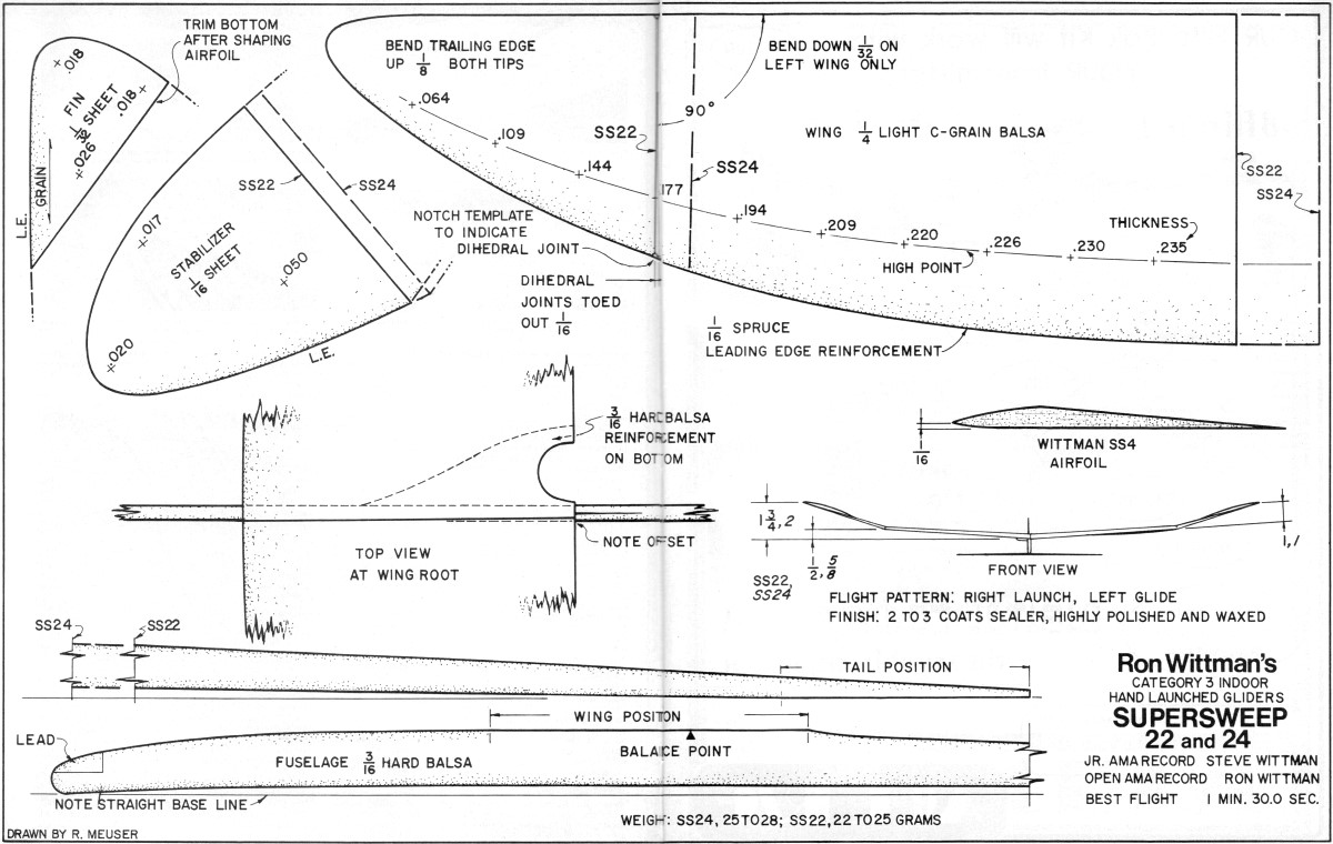
The Supersweep incorporates distinctive design features that might be applied
to any design to advantage. The most noteworthy features of the design are the airfoil
section, the high aspect ratio pointed-tip wing planform, the manner in which the
thickness tapers toward the paper-thin tips, and the severe wash-out in the wingtips.
The design of the glider, however, is only one of many factors required for success
in IHLG. Other important factors include: the construction and finish, proper trimming
and adjustment, the athletic factors - strength, stamina, and control - that result
in a powerful, consistent launch, and a long list of psychological factors including
the will to improve, and the persistence to view failure as merely a temporary set-back.
Although there are probably a number of modelers who can build as good a glider
as Ron Wittman, I doubt if there are any who can build a better glider. Since we
have not chosen to emphasize the importance of each step as we consider it in sequence,
we do emphasize that every step in constructing and finishing an IHLG is important
and must be done with care. We strongly urge you to follow these instructions to
the letter. Then, if you think you have a better way of performing a particular
operation, or if you wish to try a different method later, you will have a point
of reference. The following description applies to a right-handed person. For lefties,
of course, everything is reversed.
Selecting The Wood: The wing, being the heaviest part of the
glider, must be made from light wood, or the glider will be overweight. A piece
1/4 x 3 x 36" should weigh no more than 30 grams; a piece 4" wide, 40 grams. If
such light wood is not available, the wing will have to be made thinner and possibly
slightly undercambered, the spruce leading edge might have to be omitted, and you
will have to be extremely careful not to apply too heavy a finish. C-grain or quarter-sawed
wood - the kind showing iridescent specks on the surface - is ideal. The wood should
be flat, and the grain should be straight and parallel to the edges. The piece should
balance very close to its center. If a piece of uniform density cannot be found,
the heavy end should be toward the left wing tip, and the hardest edge should become
the leading edge. Usually, suitable 4" wide material is not available, so the wing
blanks must be made by gluing two narrower strips together. Be certain that the
edges to be joined are straight and square. Use a white glue - Franklin Titebond
is an excellent one.
For the tail surfaces, perfectly flat C-grain wood is essential. The wood should
be light, but not so light as to be flexible or mushy. Lack of flatness or stiffness
will cause the tail surfaces to deflect or vibrate during the 80 mph launch, and
that will decrease the launch altitude, or result in a smashed glider.
For the fuselage, select a piece of stiff, medium weight straight-grain 3/16"
balsa sheet, preferably with some showing of C-grain. Compare the weight, stiffness,
and straightness of several pieces, and select a piece that is as stiff as possible
but not too heavy. It is difficult to set down hard and fast rules; selecting fuselage
wood requires judgment that can be gained only by experience. The finger brace can
be made from scraps of the same piece.
Laying Out The Parts and Cutting To Outline: Make cardboard
templates for the wing and tail surfaces. Transfer the outlines to the balsa by
tracing around the template with a ballpoint or sharp nylon-tip pen. For the wing
and stabilizer, only a half-template is required (flip the template to get both
sides). Note that the wing is to be made in one piece, then cut into four sections
and rejoined after the sanding has been completed.
Cut all of the parts to shape, using a power jig saw or a new single-edged razor
blade. The blade must be sharp, or it will tear or compress the soft wood. Cut no
closer than 1/32" to the outline, then block-sand each part to its final outline
using 320 garnet paper. Using the template, mark the centerline of the wing. Balance
the wing blank along the centerline, and turn the blank so that the heavier side
becomes the left wing.
The spruce-reinforced leading edge is well worth the effort it takes to apply,
provided that the model is not in danger of being overweight. It minimizes damage,
and makes it easier to accurately form the front portion of the airfoil. A piece
of 1/16 x 1/8" spruce is glued, to the leading edge, flush with the bottom surface.
When the sanding of the wing is completed, only a hair over 1/16" of the original
1/8" depth remains. Soak the spruce in water first, or simply pre-curve the spruce
by drawing it between the fingers. This will place smaller demands on the strength
of the glue joint. However, as the curvature of the leading edge of the Supersweep
is gentle, this process is not essential.
Sanding: Make two balsa sanding blocks, each 3/4 x 3 x 11".
Round off the long edges slightly. Each side of the block is covered with paper
of a different grit number. No. 180 and 280 garnet paper are used for rough and
final shaping, while 320 and 400 "wet or dry" silicon carbide paper are used for
final thinning and smoothing. This stuff is expensive. Don't use a cheaper grade.
Ordinary "flint" sandpaper is far less suitable.
Cut the paper into strips 1/2" wider than the sanding blocks. Stick it to the
block with contact cement and wrap the edges up around the sides of the block. While
balsa is about the softest material anyone would think of using sandpaper on, it
dulls sandpaper rather quickly. Replace it as soon as it begins to lose its cutting
ability or becomes clogged.
A modeler's razor plane can be used to rough-out the top of the wing and the
fuselage, but it cuts too fast to use for shaping the tail surfaces. Use a new blade.
Hold the plane at an angle to the direction of the cutting stroke. Soft balsa is
difficult to plane. If it doesn't plane smoothly, or if it leaves streaks of uncut
wood, forget the plane and use sandpaper for the whole job. Don't use a thin blade,
a hollow-ground blade, or a stainless steel blade. Since Gillette made their Blue
Blades "super," the best blades are industrial paint-scraper blades.
Any good book on woodworking, some books about model planes, and your next-door
neighbor, will tell you that the proper way to sand is parallel to the grain of
the wood. Hogwash! Sand directly across the grain, at an angle to the grain, or
with a circular motion. If you sand with the grain, the balsa comes off in long
strings that simply clog the sandpaper and compress the wood.
Use as coarse a grit as you can get away with. Switch to a finer grit only when
the coarser grit cuts too fast for good control. Beginners often switch to a finer
grade too soon in an attempt to get a smooth surface; then, finding progress is
too slow, they bear down and crush the surface fibers of the wood. Never bear down!
That will compress the wood. It will expand later and ruin the airfoil shape. If
you feel you aren't making sufficient progress, go back to a coarser grit, replace
the sandpaper with fresh stuff, or go watch TV until you get over the feeling, but
never bear down!
All sanding should be done while the part is held against a hard, flat, clean
surface. A piece of 1/4" plate glass with at least one edge ground straight and
true is ideal, but it can be dangerous. A lamp placed under the glass will aid in
judging the thickness as the sanding progresses. Alternatively, simply hold the
piece up to the light to check the thickness, but do it often! A Formica-covered
sink cut-out, sometimes available at cabinet shops or lumber yards, is good too.
Wing and Tail Surfaces: Sand the bottom surfaces of the wing
and stabilizer blanks perfectly flat and smooth, first using 320 paper, and finally
400. Be especially careful not to round-over the edges or the tips. Mark a line
along the leading edge of the wing exactly 1/16" above the bottom surface (a cabinet-maker's
marking gage does the job nicely). Sand the upsweep of the bottom of the leading
edge. The upsweep starts 3/8" back from the leading edge and curves up uniformly
to the marked line. To avoid tearing off the spruce strip, it is best to sand toward
the wing.
Before shaping the top of the airfoil, sand the wing to the proper thickness
at each station, as shown on the plan. Note that the taper toward the tips is quite
severe compared to other gliders, and that the tips are quite thin and fragile.
Using a cardboard template, draw a line on the top surface with a nylon-tipped
pen to indicate the high point of the airfoil.
Next comes the most critical part: shaping the top of the airfoil, it is essential
that the high point be kept sharp. I had difficulty doing that, until I started
using the following method. (Ron sands the top surface freehand without recourse
to such crutches as this, but I don't have his dexterity.)
Secure a strip of masking tape to the top of the wing, so that the rear of the
tape is along the high-point line. Sand the rear portion of the wing to shape. The
tape will not only serve as a guide, but since it does not sand as readily as balsa,
it will prevent accidental cutting into the front part of the airfoil. Note that
the top of the airfoil is a straight line from the high-point to the trailing edge.
If you accidentally sand into the tape, replace it.
When the aft portion of the airfoil is completed, remove the tape - carefully,
so as not to rip up shreds of balsa - and apply masking tape with its front edge
aligned on the high-point line. Then sand the front part of the airfoil in a uniform
flat curve down to the marked line on the leading edge. Note that the leading edge
is sharp. The shape of the airfoil section is extremely critical, so refer to the
plans.
Sand the top of the stabilizer to the prescribed thickness, then sand in the
airfoil shape. Sand the rudder similarly, but work back and forth from one side
to the other to ensure a symmetrical section.
Ron doesn't actually measure the thickness of the parts. He knows by the feel
of the parts. He knows by the feel of the part, and by how the light shows through
it, when he has the part to the thickness he wants. But, in order to duplicate Ron's
Supersweep, you will have to measure the thickness somehow. A one-inch micrometer
caliper would work, except for the fact that the throat of the mike is often not
sufficiently deep. The throat can be ground deeper, or a 1/4" extension can be cemented
to the fixed anvil so that the deepest part of the throat is utilized.
A less expensive alternative is to use a machinist's outside spring caliper and
a ruler with fine divisions. To prevent the tips from gouging the glider parts,
balsa "feet" may be epoxied to the tips. Still another way is to measure from the
work surface up to a straightedge laid across the top of the wing (equalize the
measurements on both sides). The proper thicknesses of the various parts are indicated
on the plans.
Fuselage: Sand the fuselage to an oval cross-section. Be sure
not to round the edges in the regions where the wing and stabilizer are to be glued.
Here is how you can check to determine whether the fuselage has been sanded down
enough: - or too much! Clamp the fuselage to a table with the trailing edge of the
wing mount at the edge of the table. Hang a 100 gram (3 1/2 oz.) weight on the tail
boom at the stabilizer LE position. The extreme end of the boom should deflect no
more than 1/2".
The next step will be the most difficult. Take all the finished components, put
them in a safe place, and wait for the October issue of AAM. Don't attempt to glue
anything together, since there are subtle techniques involved, especially Ron's
"magic potion" finishing techniques. If you are impatient, make a duplicate set
of parts and complete an SS your way. Next month, finish one Ron's way and compare
them. You'll be shocked at the difference proper methods can make in better flight
time. Until next month, happy hand chucks!

<click
for larger version>
Notice:
The AMA Plans Service offers a
full-size version of many of the plans show here at a very reasonable cost. They
will scale the plans any size for you. It is always best to buy printed plans because
my scanner versions often have distortions that can cause parts to fit poorly. Purchasing
plans also help to support the operation of the
Academy of Model Aeronautics - the #1
advocate for model aviation throughout the world. If the AMA no longer has this
plan on file, I will be glad to send you my higher resolution version.
Try my Scale Calculator for
Model Airplane Plans.
Posted June 8, 2012
|