|
The "Topper"
is a general purpose control line stunter with a profile fuselage, a built-up wing,
and power provided by a Fox .25 engine. Designed by John D'Ottavio, it originally
went by the name of "Falcon," as evidenced by the lettering on the model flown by
Eddie Elasic in the 1961
Air Youth State Competition (AYSC) held at Willow Grove NAS. He and John combined
talents to come up with the design. It was awarded the honor of "Best 4-Way
AYSC Plane." What are the 4 ways? I see endurance, speed, and stunt, but I'm
not sure what the 4th way is - combat, maybe?
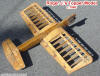 News Flash (10/27/2013): Website visitor
Roger J. wrote to tell the story of how he inherited an unfinished Topper control
line model from his uncle. He was kind enough to send a photo of the airframe. Roger
intends to complete the build based on the plans shown at the bottom of this page.
Hopefully, he will send a photo of the completed model. News Flash (10/27/2013): Website visitor
Roger J. wrote to tell the story of how he inherited an unfinished Topper control
line model from his uncle. He was kind enough to send a photo of the airframe. Roger
intends to complete the build based on the plans shown at the bottom of this page.
Hopefully, he will send a photo of the completed model.
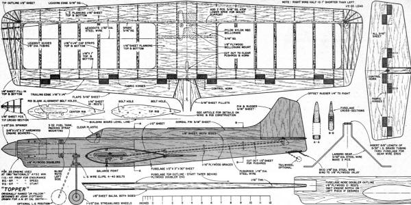
"Topper" Article and Plans
Best 4-Way" AYSC Plane
John D'Ottavio Designer of "Topper"
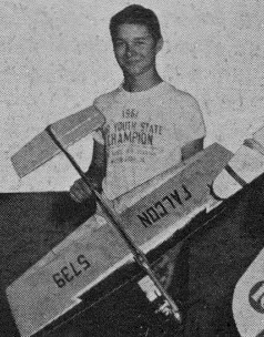
Eddie Elasic with Falcon, aka Topper. Flying "Topper" at the
1961 AYSC Nationals, Eddie Elasick placed first in stunt scoring, second in beauty
and sixth in both speed and endurance. These together added up to the grand championship.
As a capper Eddie went on to win a fifth place in Junior Precision Acrobatics in
the 1961 National competition.
Willow Grove NAS: America's Best Youthful Flyers
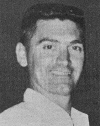
John D'Ottavio
John D'Ottavio, interested in modeling for over 25 years, has specialized in
control-line stunt flying, winning many Eastern contests. His designs have been
widely publicized and he is an active member of three N. J. model clubs:
Flyateers (Rich's Hobbytowne), Union M.A.C., and Garden State Circle Burners.
As if this doesn't keep him busy enough, he also manages the Roxbury, N. J., Little
League! The D'Ottavio's are another modeling family. The older boys, John, Jr. (14),
Mickey (12), and Phil (8) are all sprouting model wings while a younger pair, Victor
(4) and Donna (2), will soon join the fun.
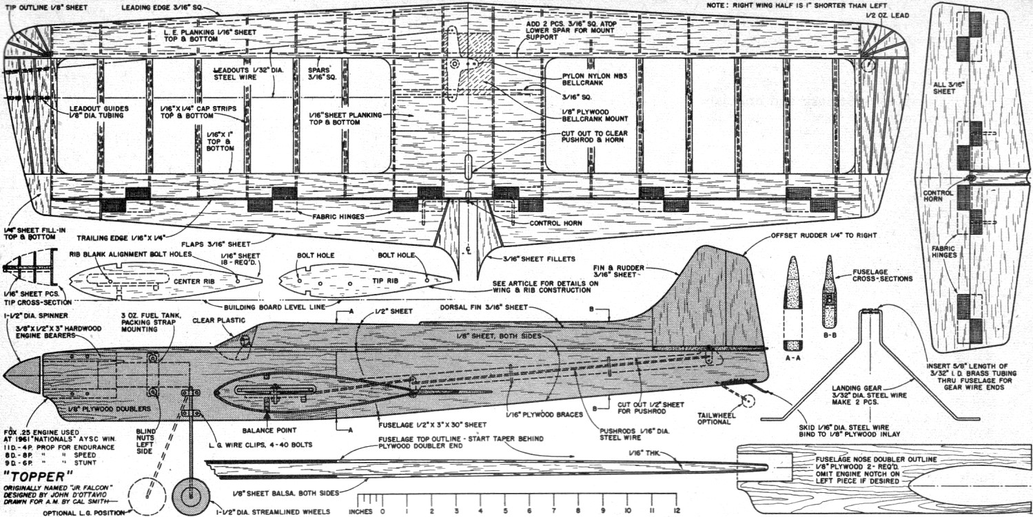
D'Ottavio's design is a no-nonsense profile stunter. Its built-up wing has a
thick symmetrical airfoil and flaps. Tails are sheet balsa. Fuselage is 1/2" sheet
with plywood and balsa doublers running full length. Control system is fully enclosed
for cleanness. Power was a stock Fox .25, a year old at the time of the Nationals.
Any engine up to allowable .35's can be used. Bearer spacing may have to be changed
if you shift to a different engine.
Wingspan is 37-in.; length, 31-in.; wing area, 350 sq. in.; weight, 28-oz. Fuel
tank is a standard 3-oz wedge; spinner diameter is 1 1/2 in. Top-Flite and Tornado
propellers in various sizes were employed for best performance in each flying phase.
An 11D-4P prop was used for Endurance; 8D-8P for Speed; 9D-6P for Stunt. Fox Super
fuel was in the tank.
Like to build "Topper" for that 1962 AYSC competition? Good! Then read on. Construction
starts with the wing since it must be completed before joining to the fuselage.
Begin by cutting out the wing ribs. Make one center and one tip rib pattern from
thin aluminum, heavy card stock, or 1/16" plywood from the outlines shown on the
plan. Note the blank alignment bolt holes near leading and trailing edge. These
should be accurately spotted to insure uniform taper of the ribs. Cut 18 rib blanks
from 1/16" sheet slightly oversize. Stack 9 blanks between the center and tip rib
patterns, drill and bolt together with two 4-40 bolts. Carve and sand the blanks
down flush with the patterns. Cut spar and L.E. notches. Repeat procedure to make
ribs for the opposite wing half. Notch two center ribs for the 3/16" sq. spar supports
and cut out one center rib for bell crank clearance. Also punch 1/4" dia. holes
through left half wing ribs for the leadout wires. Locate the hole position by referring
to the wing plan. The right wing half is 1" shorter than the left so the tip rib
for this side should be discarded and a duplicate of the next to last rib made.
This rib should be reduced slightly in outline to maintain taper.
Since the wing is tapered it will be necessary to block up the tip ribs 3/32"
above plan and building surface. Cut a couple dozen scrap wedges to aid in blocking
up spars and trailing edges during assembly. Build wing UPSIDE DOWN directly over
plan. This will permit access to center section for bellcrank and control installation
later. Put down upper spar, space out ribs and add leading and trailing edges. Align
and block up carefully so that the structure is flat with no twists. Add lower spar
and let this assembly dry thoroughly.
Add 1/16" x 1" trailing edge planking and 1/16" sheet leading edge planking.
These can be one piece from tip to tip since taper is so slight. Add 1/16" x 1/4"
cap strips to ribs. Do not cover center section now. When this assembly is thoroughly
dry, it can be taken up from the building board and turned over for additional work.
It would be a good idea to block up center and tips on the building board again
to prevent twists developing while planking is added to the upper wing surface.
Add the 3/16" sq. bellcrank mount support and the plywood bellcrank mount piece.
Install bellcrank and leadout wires. Leave bellcrank pivot bolt loose so that flap
pushrod can be installed after flaps are assembled. Plank leading and trailing edges
and add cap strips to ribs. Here again omit center section planking for the time
being.
Make flaps from 3/16" sheet, join with wire type control horn and assemble to
trailing edges with fabric "Z" hinges. Add wing tip outlines, contour pieces, leadout
guide tubing and right wing ballast. Carve and sand tip pieces to a smooth rounded
shape. Now bend the flap pushrod to shape and install. Be sure that bellcrank neutral
position gives flap neutral position. When this portion of the control system is
completed and working FREELY, the bellcrank pivot bolt can be tightened down permanently
and both upper and lower center section planking can be added. Sand entire wing
structure smooth and apply two coats of clear fuel-proof dope. Sand lightly again
after doping. The wing can be covered now if desired. Silk was used on the original
"Topper." Apply silk wet and clear-dope down. Sand lightly between coats with 400
grit wet-dry finishing paper. Build up at least 4 coats of clear dope. Colored dope
should be applied after the wing is joined to the fuselage.
Fuselage construction is next. Cut 1/2" x 3" sheet to outline taken from plans.
Notch nose for engine bearers and plane thickness taper toward tail. Engine bearer
spacing shown on plans is for .15, .19 and .25 engines. Space according to your
engine. Make cut-out for wing and elevator pushrod. Add two plywood braces in aft
fuselage pushrod slot. These serve to join fuselage sheet and act as fairleads for
the pushrod.
Glue hardwood engine bearers in place and cut out the 1/8" plywood nose doublers.
Glue the doublers to balsa fuselage sides with white glue such as Elmer's Glue-all.
Clamp and let dry thoroughly. Glue the 1/8" sheet balsa doubler to ONE side .of
aft fuselage only. At this point in the construction the wing, elevator and elevator
pushrod must be installed.
Make horizontal tail surfaces from 3/16" sheet. Join stab and elevators with
wire type horn and fabric hinges. Slide wing into fuselage cut-out and pin stabilizer
in place. Enlarge wing cut-out carefully to permit passage of flaps through the
fuselage. Bend elevator pushrod to shape, slide through plywood fairleads and join
to flap and elevator horns. Check for free movement and neutral settings. When pushrod
fit is satisfactory, wing and stab glue permanently in place. Align wing and stab
squarely with fuselage. Solder retaining washers on pushrod ends at flap and elevator
horns for permanent attachment. When thoroughly dry complete the structure.
Additional instructions appear on the full size drawings available from Hobby
Helpers as Group Plan # 362A (see firm's advertisement in this issue).
 "Topper"
Plans
Notice:
The AMA Plans Service offers a
full-size version of many of the plans show here at a very reasonable cost. They
will scale the plans any size for you. It is always best to buy printed plans because
my scanner versions often have distortions that can cause parts to fit poorly. Purchasing
plans also help to support the operation of the
Academy of Model Aeronautics - the #1
advocate for model aviation throughout the world. If the AMA no longer has this
plan on file, I will be glad to send you my higher resolution version.
Try my Scale Calculator for
Model Airplane Plans.
Posted September 28, 2013
|