|
Scale
model boaters with metal machining experience might like the challenge this variable pitch propeller hub presents. A
servo is used to set the pitch angle, including a negative pitch for reversing direction. Detailed drawings are
provided for the entire assembly, but for some reason the blades themselves are not shown. Maybe it is to allow the
modeler to define his own blade size and shape to mimic the original. Recommended materials are stainless steel and
hard brass, so the unit should be rugged enough for just about any type model except for a high speed job with very
high RPMs on the shaft.
Aquativities - Variable Pitch Boat Prop
By Bill Baughman
|
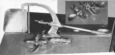
Photos show parts of original DeGear prop unit; two main hub halves are bolted around shaft and rectangular slide
which is equipped with small pins. Pins engage slots in prop hubs and by sliding back and forward, change pitch.
|
A past American Modeler carried photographs of the "Reversible Propeller" as perfected by Ed DeGear of San
Francisco. Installed and operated via a servo, this unit solves the problem of backing a gas-powered model boat. Many
varieties in boat speed in both forward and reverse directions, plus neutral, may be obtained with two channels of a
multi-channel R/C rig.
For readers desiring a duplicate, we have data and specifications for the machining of the De Gear prop from the
master himself! Ed says, "Now you have all my 'secrets.' The contraption is merely a lot of close machining with careful
use of material - and it will last a lifetime without trouble." We feel that in typical De Gear fashion Ed understates
his machining ability and model engineering skill by about 90%. This project is now for the hobbyist highly skilled
on the lathe and with other machine shop tools. This is very exacting work; Howard "Red" Barrows of Los Angeles, who
completed his version of the unit from these drawings said, "That was a machinist's nightmare!"
|
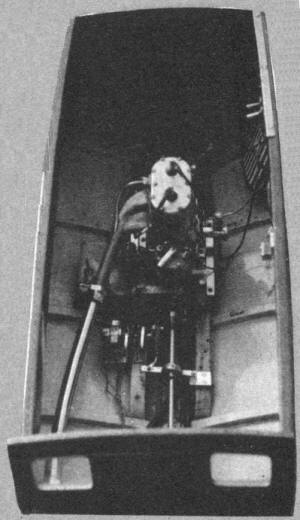
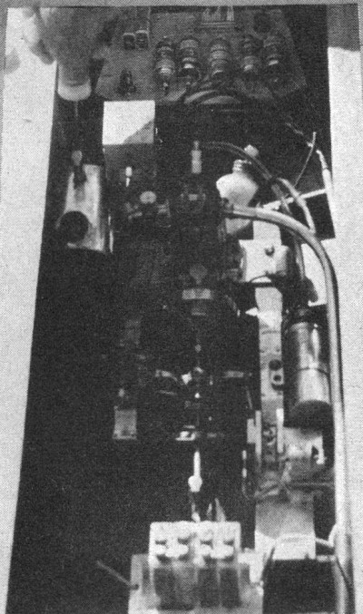
Interior of DeGear's boat with proportional R/C.

Barrows boat has similar yoke.
|
Our drawings are somewhat like
Topsy in that they have
"just growed." Originally, Ed drew up the necessary information and rough sketches in the form of a letter. Then, through
the efforts of Harry Ashton and "Red" Barrows, working drawings were prepared. These formed the basis of the finished
drawings here. They are complete with the needed information for machining, so it will not be necessary to include much
step-by-step "how to" explanation for the modeler equipped to turn out the parts. However, here are Ed's "shop notes."
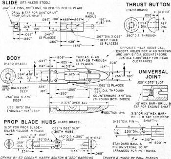
Body-hub - Start with square block; split and bolt together; drill and ream 1/4" and 3/16"
holes; working from holes, mill center recess; fit block to have 1/4" travel; free when assembled; turn O.D. after milling.
Slide, Blade Hubs, and Prop Blades - Slots engage the pins; assemble, shift shaft to about
1/3 out from full "in" position; mill blade slots at right angles to shaft when in this position; form propeller blades
so that area is about equal ahead and behind pivot; silver solder blades to hub, then shape hub.
The photographs will help you understand how everything is installed in your boat. In operation, the servo inside
the hull operates a yoke, which utilizes a ball bearing holding shaft within the yoke. The yoke slides the propeller
shaft forward and back. Since the hollow propeller hub is bolted together around the machined ridge in the thrust button
which is an integral part of the strut, the propeller shaft slides forward and back inside the hub. The pins which are
a part of the slide attached to the after end of the propeller shaft, fit in the slots machined in the blade hubs located
inside the whole hub unit. By the movement of the shaft, these pins slide forward and back, thereby changing propeller
pitch.
The unit has undergone two versions of one minor modification ... Ed originally tried a ball thrust bearing within
the strut unit itself per the photos of the original. This proved faulty due to the action of rust on the bearing. He
improved his installation by eliminating the ball bearing in the prop to strut connection and thrust' is now taken through
a tube to a ball bearing inside the hull.
Barrows' version has another approach and it is the one in the drawings. "Red" silver-soldered the thrust button
shown (which is similar to Ed's and gives the overall hub part a streamlined configuration) to the strut body, thereby
carrying the thrust load at the strut on a common bearing surface, eliminating the ball bearing at that point. This
modification, in use for some time, does a good job and is comparatively simple to fabricate and install. So, take your
pick.
The conventional scoop type water pick-up which utilizes the propeller to force water through the engine cooling
system cannot be used in a boat that is to be backed up. To overcome this, Ed and Red both have a miniature water pump,
driven by a pulley arrangement on the propeller shaft. In this manner, water is pumped to the engine whether the boat
is going forward, backing, or sitting still in neutral. Another consideration should be the servo used to operate the
reversing system. DeGear and Barrows custom built servos to handle the task. They are both very powerful. Undoubtedly
some commercial servos will do the job, but to date none have been used so data cannot be included on such an installation.
Variable Pitch Boat Prop Plans
Posted May 24, 2014
|