|
Believe it or not, there was
a day when building your own electronics was a good way to save money if your budget
was smaller than your appetite for R/C systems, radios, even TV sets. Heathkit comes
to mind for all us old-timers as a source of pre-kitted products, but like most
electronics companies of yore, they no longer offer kits; it is much cheaper to
have complete systems built overseas. Besides, modern components - resistors, capacitors,
ICs, etc., are far too small for most people to work with successfully. Here is
a two-part article from the April and May 1972 editions of American Aircraft
Modeler magazine showing how it was done with a custom 2-channel digital proportional
radio control system dubbed the AAM Commander. It still makes a good read because
of the theory of operation that is covered.
AAM Commander Radio Control System
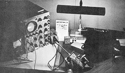
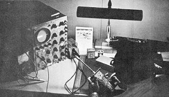 Using a Tektronix 435 scope, Fred Marks
checks encoder pulses. Scope is also capable of showing modulation patterns at 27MHz.
Part I (see
Part II,
May 1972 AAM)
You can make the two-channel digital system which offers reliability, performance,
goof-resistant assembly, and low cost by extensive use of integrated circuits.
By Fred Marks
It seemed to us two years ago that our readers would be interested in the presentation
of a two-channel digital system that would satisfy the needs of the car, boat, glider
and sport power plane fans. AAM asked me to undertake the project and to try to
make it as simple and goof-proof as practical. The project is finally complete and
we are pleased to present the results.
I n accordance with the above basic requirements, the following more specific
objectives were set. The system should be as technically up-to-date as possible;
have the maximum flexibility; be the utmost in simplicity with no frills added;
and, taking advantage of inherent digital system characteristics, it should have
a growth factor for those who would wish to expand the system later.
Achieving the first objective is by far the most difficult, for technology is
a galloping horse. One must finally decide to jump aboard and go. This process led
to several recycles and ultimately to the point that everything in the system, except
the transmitter and receiver RF
sections, utilize integrated circuits. The encoder, decoder, and servo amplifiers
are all composed of integrated circuits. The use of bridge-type servo amplifier
permits a two-wire power pack for the receiver and three wires for each servo.
 The second objective is the most satisfying
of all, as the system has been successfully tested in cars, boats, gliders and power
planes. The receiver and decoder are compatible with any transmitter on the same
frequency, from one to eight channels. The decoder simply decodes the first two
channels that it sees, usually aileron and elevator, and ignores the rest. It will
operate any servo made today (provisions are made for battery center-tap wiring),
including those requiring a negative going pulse. It has been tested with the following:
EK MM3; Orbit PS-4; Micro Avionics; all Kraft servos; Controlaire S4b, S4d, 5-5
and 5-6; Min-X; Digiace; MRC F-700 and F-710; Royal Electronics; Pro-Line; Heathkit
PS-9 and I C servos; Larson, and others. The second objective is the most satisfying
of all, as the system has been successfully tested in cars, boats, gliders and power
planes. The receiver and decoder are compatible with any transmitter on the same
frequency, from one to eight channels. The decoder simply decodes the first two
channels that it sees, usually aileron and elevator, and ignores the rest. It will
operate any servo made today (provisions are made for battery center-tap wiring),
including those requiring a negative going pulse. It has been tested with the following:
EK MM3; Orbit PS-4; Micro Avionics; all Kraft servos; Controlaire S4b, S4d, 5-5
and 5-6; Min-X; Digiace; MRC F-700 and F-710; Royal Electronics; Pro-Line; Heathkit
PS-9 and I C servos; Larson, and others.
The servo has not been as extensively tested in other installations, but thus
far has proven to operate satisfactorily with systems using IC decoders and with
the Heathkit system which has an SCS decoder.
The transmitter will operate one or two channel receiver/decoders but, obviously,
is not designed to provide additional channels at this time. It may be safely operated
on from B to 12 volts with range dependent on voltage. The nominal design voltage
is 9V, which provides out-of-visible-sight range. However, one may operate boats,
cars, or small sport airplane models on BV (seven nickel cadmium cells give B.4V).
The receiving system is designed to operate on 4.BV using four nickel cadmium cells,
although alkaline energizers may be used. (Carbon-zinc pen-cells are not recommended
for this or any other system.)
Simplicity was achieved by the use of inexpensive ICs. They offer two distinct
advantages to the home or kit builder: (a) their use permits a drastic reduction
in the number of solder joints required, and (b) every IC is tested by the manufacturer
(this is not done for discrete components such as transistors). The transmitter
is further simplified by: the elimination of a metering circuit; the use of an external
battery charger, if any; the necessity for only one stick assembly; and the need
for only two tuning points. The receiver is simplified by relieving it of the normal
clock and sync pulse forming functions. These functions are performed, instead,
by the IC on the decoder. The use of the two-wire power supply eliminates approximately
10 points for potential failure.
 The final objective, i.e.,
potential growth, is not difficult since any digital system is modular. By building
two additional servos, changing to a new decoder board which retains all components
except for a new IC, adding a new transmitter encoder board which has one IC, four
capacitors, two resistors, and of course, a second stick assembly, a four-channel
system is produced.
To insure that the system was designed properly and that performance was optimized,
the following procedure was employed. The basic system was developed by first designing
the decoder, interfacing it with a well-known and tested receiver operated by a
six-channel transmitter. The transmitter was breadboarded and verified on the bench;
a P.C. layout was then made and three prototypes constructed. This setup was tested
extensively using existing servos.
 A considerable amount of effort was expended
in the development of a suitable servo amplifier. Center-tap amplifiers using an
ML 85 IC were tried and rejected, as was a design using a Darlington amplifier in
each drive leg:
Amplifiers using a Schmitt trigger in each drive leg were tried but we couldn't
achieve the goal of placing the servo amplifier on a single board in the smallest
servos. Finally, the World Engines IC chip was selected for the servo. This seems
to be ideal and only has the disadvantage of requiring an 11 ohm motor.
 The final problem attacked was the receiver
design. We first attempted to use the ready-made ACE Micro Gem receiver modified
to add AGC. This performs quite satisfactorily in "cars and boats but does not provide
a sufficient margin of performance for planes. It then became necessary to begin
the design of a new receiver which could take advantage of the IC decoder. This
done, three prototype units were tested extensively in a two-channel 0.10-powered
model called the Flexible Flyer. In order to insure repeatability of the system,
artwork and construction instructions were completed and a "pilot" run of ten systems
was performed by local modelers.
"While the preceding cannot absolutely assure that one will never experience
a glitch, it is felt that system performance is well verified.
Another important point, not only for this, but for any digital system whether
kit or not, is "In case of difficulty .. ." Except for checks of DC voltage, presence
of RC output, and verification of transmitter operation using a monitor, an oscilloscope
must be available to the builder of any digital system if he is to perform his own
troubleshooting. Actually, troubleshooting is quite simple if one can use a scope
and knows what the traces should look like. Insofar as practical, this information
will be presented, not just to help the builder of the AAM Commander, but also as
a means of showing the reader how digital systems work.
 It can be hoped that a spark may have been
kindled to assemble a complete system (transmitter, receiver, decoder, and two servos)
or part of the system for use with an existing system. Here is the planned sequence
for the "AAM Commander: I n this first part of the series, we have described the
system in general, and will now present the printed circuit layout, list the components
required, describe how they may be obtained, give the drawings for the subassemblies
which may be readied for later use, and provide other information useful for getting
started. The second of the series will present the schematics, block diagrams, design
information, and instructions for assembly of the transmitter "and the servo amplifier.
The third part of the series will present the schematics, block diagrams, design
information, and instructions for assembly of the receiver and decoder. At the completion
of these, an entire flyable system will be achieved. To aid in better understanding
the system and, as an informative item, the final article will: present system integration
procedures; show how parts of the system may be used with other systems; provide
trouble-shooting procedures; and indicate changes required for expandability.
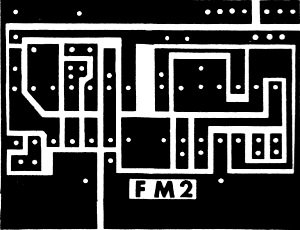
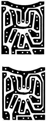
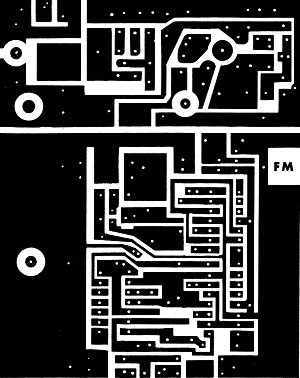 Figure 1 presents a full-size print of the
printed circuit layout for the complete system. I n order to make the necessary
boards, have a film negative made of the P.C. layout. This is done by photographing
the P.C. drawing layouts on page 53 and having a film negative of this made to the
exact same size as presented in the magazine. Special arrangement has been made
with AAM's plans service to supply the film negatives for $1.00 per set. These may
be ordered by writing to me c/o AAM or directly to the Editor. Purchase one sheet
of 6"x6" pre-sensitized P.C. board (Kepro S66G was used to make the pilot systems).
Also needed will be one pint of P.C. emulsion developer (trichlorethylene) and etchant.
Either ferric chloride or ammonium persulphate may be used. These three chemicals
may be purchased from a chemical supply house-perhaps the local druggist can suggest
one. One may also purchase the Kepro kit for P.C. boards, which has the necessary
chemicals, or purchase them packaged separately from Kepro.
The sensitized P.C. board is not extremely sensitive to light but must not be
exposed to direct light. Use a red lamp while working to set up for exposure. Make
everything ready (except for actual board exposure) before opening the package of
sensitized board. A lamp socket fitted with a 750-watt photoflood bulb, a pane of
glass, and two weights will be needed. Pour the developer (not the etchant) into
a shallow pie tin. Turn off all lights except the red lamp. Place the P.C., board
on a table (copper side up), and lay the P.C. film negative over it-the letters
FM must read properly or the boards will be made backwards. Place the pane of glass
over the negative and hold in place with weights. Turn on the 750-watt photoflood
and expose the board for five minutes from a distance of 7 to 10 in. Place the board
in the developer (trichlorethylene) for one minute; agitate while developing. Remove
and permit the board to dry for at least 10 minutes. Do not touch and do not blow
on the board.
 Etch the board in ferric chloride or a solution
of 3 oz. of ammonium persulphate per pint of water. (The latter is preferred because
the solution is nearly clear, whereas ferric chloride is quite opaque.) The process
may be speeded considerably by heating and by agitating the solution. Up to 1800
is adequate-it should not boil. About 15 minutes etching time should suffice. It
takes much longer at room temperature. Inspect the boards carefully for unetched
material which might cause a short. If patience permits, a check between each land
and all adjacent lands with an ohmmeter will insure absolutely against such shorts.
The boards are glass epoxy so any attempt to drill with anything less than carbide
steel bits is a waste of time. A No. 64 carbide steel drill bit can be used if a
very true running collet chuck is used in a Dremel or other high-speed tool. However,
bit breakage is a problem. It was found that a No.1 carbide steel, round dental
burr fits one of the Dremel collet chucks perfectly and is at least an order of
magnitude better than regular drill bits because the shank is about 3/32 in. diameter
for excellent stiffness. One bit should drill all the holes needed. Such bits can
be obtained from your dentist's supplier. Larger holes will be drilled in the few
places needed during construction.
Shear the boards, if possible, on a shear used for P.C. boards or on a foot shear
used for sheet metal. As a last resort, tin shears will do. Work slowly and be sure
the outside line is used for cutting. Haste will make a handful of wasted board!
File and/or sand carefully to the final shape. This completes the P.C., boards.
Set aside in paper toweling or plastic, where they can't be marred, until needed.
 Having procured parts for the pilot models,
we have an excellent feel for the job of rounding them up. It is asking for trouble
to substitute parts even if
you think you know what you are doing, particularly in the case of the semiconductors.
No matter what anyone says, the general replacement lines of transistors will not
work. Don't buy them! The most general source of supply is through the Allied Industrial
Catalog, if there is no industrial supplier in your vicinity. Most of the transistors
used are made by Motorola, as are the IC, and are generally available from an electronic
wholesale firm.
We are happy to report that arrangements have been made with ACE R/C Inc., Higginsville,
Mo. 64037, to kit the system. In addition, ACE will include all the individual components
in their 1972 catalog. While one may procure all parts and build the system from
scratch, the chore is made much easier by obtaining the kit units. The OEM manufacturer
for items is identified on the parts list for those able to obtain parts directly
through a distributor.
The following information may help in obtaining components for any project, and
to aid in building kits.
Resistors
 The resistors used in the system are 1/4
watt composition types that are 10 percent tolerance. There is only one exception-one
1/8 watt resistor is used per servo. There are four colored bands around the bodies
of all the resistors. These will be discussed as the first, second, third, and fourth
colors. The fourth color is always silver or gold, while the first color is never
silver or gold. Thus, the first color band is quite simple to distinguish. In addition,
the first color band is usually closer to the end of the resistor body than the
fourth color.
The fourth color identifies the tolerance of the resistor; gold is 5 percent
and silver is 10 percent. All the resistors used in the : AAM Commander have a silver
band. The colors of the other three bands are identified by the following resistor
color code:
Color Number
Black 0
Brown 1
Red 2
Orange 3
Yellow 4
Green 5
Blue 6
Violet 7
Gray 8
White 9
The preceding identify the value of the resistor, in ohm's, as follows: (a) The
first band gives the first digit of the resistance value; (b) The second band gives
the second digit of the resistance value; (c) The third band gives the multiplier
for the value, i.e., the number of zeroes which must be added.
As an example, consider a 270 ohm resistor; the first band is red, for a two,
the second is violet, for a seven, and the third is brown for addition of one zero.
A 15,000 ohm resistor is identified by brown (one), green (five), and orange (three
zeroes). In the schematics, large values may have the multiplier 1000 identified
by a k, such as 15k for 15,000 ohms, etc.
Capacitors
The marking of the tantalum capacitors is quite clearly stated; however, disc
capacitors may have varying markings. The capacitor will always have two, three,
or four digits indicating the value of capacitance. However, there is inconsistency
in the characters that follow the digits. For example, a 10 picofarad (10pf), which
is the same as 10 micromicro farads, may have only the number 10 printed on the
body. A 2S0pf may be marked "250Z," a 47pf may be marked 47k and a 0.05 microfarad
(mf) may be marked 0.05. Nevertheless, the basic value is always marked; the difficulty
is in determining the multiplier, if any. The following will be useful in determining
the value:
Value in pf Same Value in mf
1000
0.0010
2200
0.0022
4700
0.0047
5000
0.0050
Most of the values which are .01 or larger are simply identified that way. Quite
often, disc capacitors will have markings to identify the voltage rating such as
10v or 1 kv: do not confuse this with the value of the capacitors.
The physical size of the capacitor will be determined by its capacitance and
the voltage rating. It is desirable to stick to the physical sizes to be shown on
the overlay drawings, otherwise things won't fit.
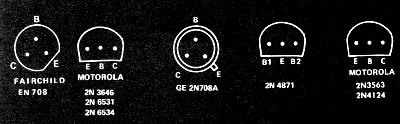
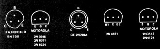
Transistors
The basing arrangement for transistors varies. Figure 2 presents the basing for
transistors which will be used in the system. It is hoped that the preceding data
will be posted above the work bench during construction.
As indicated earlier, the transmitter and servo will be constructed first. There
are some preassemblies that can be done before transmitter construction is started.
These subassemblies are shown in Figure 3.
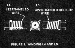
Wind L4 and LS on the CTC 2173-3-3 coil form as shown in Figure 3. The technique
to be used is as follows: Using two pair of pliers, grip the ends of a 24-in. length
of No. 22 enameled wire and stretch slightly to straighten and "set" the wire. Scrape
1/4 in. of enamel from one end of the No. 22 enameled wire and solder to terminal
No.1 of the coil form. Strip 1/4 in. of insulation from one end of a 24-in. length
of No. 22 stranded hookup wire. Solder to terminal No.3 of the : coil form. Coat
the area of the-coil form onto which the coils are to be wound with S-minute epoxy.
Wind simultaneously, Clockwise viewed from the top, both the enameled and hook-up
wire as shown in Figure 1. Note that the hookup wire proceeds 1/2 turn to terminal
No.1 before winding of L4 starts. Wind both until about 8 turns are on the form.
Hold the coils in place until the epoxy sets; the wires can be unwound as needed
with no difficulty.
Working carefully, unwind the hook-up wire until 5-3/4 turns are on the form,
i.e., count up 5 turns from terminal No.3, then on around 3/4 turns to terminal
NO.4. Bring the hook-up wire straight down, strip 1/4 in. and tin, then solder to
terminal No. 4 to complete L5. Unwind the enameled wire until 6-3/4 turns remain,
i.e., count up 6 turns from terminal No.1, then proceed 3/4 turns more to terminal
No. 2 for a total 6-3/4 turns. Bring the wire straight down, scrape 1/4 in. of enamel
at the junction to terminal No.2 and solder. This completes L4. Recheck the completed
coils against Figure 3. The epoxy will hold the coils in place.
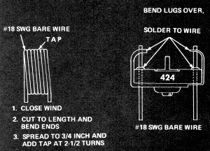
Wind L7 as shown in Figure 3. The middle size X-acto knife handle is exactly
the right size (approximately 1/2 in. diam.) form to wind L7 on. Wind exactly 7
turns of No. 18 enameled or bare wire, bend the ends straight down, and clip to
1/4 in. Remove from the X-acto handle and carefully spread all turns evenly until
the coil is exactly 3/4 in. long. Add the tap at 2-1/2 turns from the end as shown
in the overlay drawing. Set aside until needed.
Prepare the antenna trimmer C 18 as' shown in Figure 3. This is done to provide
solid mounting for C18 with the adjust screw accessible from the pc side of the
board. Set aside until needed.
Suppliers
ACE R/C
Higginsville, Mo. 64037
Royal-Electronics Corp. 2119 S. Hudson St.
Box 22204
Denver, Colo. 80222
World Engines, Inc. 8960 Rossash Ave. Cincinatti, Ohio 45236
Components, Inc.
(order through ACE R/C. Royal Electronics, World Engines, or from Doss Electronics,
Inc.
6660 Security Blvd.
Baltimore, Md. 21207
(Doss has a $25 min. order)
Sprague, Motorola, Fairchild, GE, CTC, Switchcraft, Elemenco, CRL, Belden, Miller-National
(order though Allied Radio)
D & R Products
27635 Forbes Rd.
Laguna Niguel, Calif. 92677
Posted March 8, 2023
(updated from original post
on 2/3/2013)
|