|
Do a Google search on "variable inductance servo" or "inductive
feedback servo" and you will not find anything useful. That alone
these days is sufficient to prove that the concept never caught
on in popularity. I don't think it is because the configuration
is not good, it is just that the problems associated with early
potentiometer feedback elements were solved long ago. Prima facie
evidence of that is seen in the millions upon millions of servos
sold yearly for model airplanes, helicopters, cars, boats, and drones.
They all use servos with potentiometers mechanically coupled to
the rotating output shaft.
|
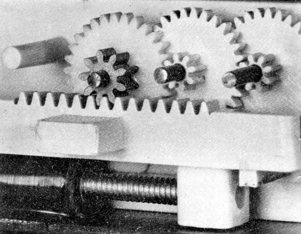
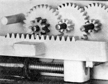
Rotary output servo gear train.
BTW, before you are tempted to dismiss the cosine relationship
as not being exponential, recall that the Euler identity
for cosine is shown above.
|
That said, this article is an excellent example of research and
development performed to solve a serious problem and coming up with
a workable solution. Many alternatives were tried, including capacitive
feedback and optical feedback. Size, weight, and reliability finally
excluded all but the variable inductor.
 I
will take this opportunity to say that I have never understood why
the servo industry adopted the rotary output (rotating shaft) configuration
rather than the linear output (sliding). Because pushrods direct
force approximately along a straight line, more movement is produced
near neutral rotational displacement, then tapers off according
to cos θ as the transmitter control stick is moved. Typical
servo rotation is ±60°, so the linear transformation
ranges from nearly 1:1 around 0 to 0.5:1 at 60°. Modern computer
radios offer the ability to programmatically cancel out that response
using what is termed 'exponential
response'. This is necessary because the flier usually wants
less responsiveness near neutral and more near the extremities because
the model flies more smoothly. I
will take this opportunity to say that I have never understood why
the servo industry adopted the rotary output (rotating shaft) configuration
rather than the linear output (sliding). Because pushrods direct
force approximately along a straight line, more movement is produced
near neutral rotational displacement, then tapers off according
to cos θ as the transmitter control stick is moved. Typical
servo rotation is ±60°, so the linear transformation
ranges from nearly 1:1 around 0 to 0.5:1 at 60°. Modern computer
radios offer the ability to programmatically cancel out that response
using what is termed 'exponential
response'. This is necessary because the flier usually wants
less responsiveness near neutral and more near the extremities because
the model flies more smoothly.
A linear output servo addresses three negatives: 1) it removes
the nonlinear nature of the control surface deflection, 2) the rack
and pinion gears driven by a worm gear isolates the motor from the
reverse forces placed on the servo control arm, and 3) battery power
is not required to counter the aforementioned reverse force on the
motor (otherwise the motor might be momentarily
backwards to hold the control surface in position). There
must be a good reason for it, though. Melanie suggested maybe there
is an all-encompassing patent on the linear output servo that would
make licensing and manufacturing prohibitively expensive. I welcome
input regarding this issue.
The Variable Inductance Servo
John Cline, Engineer, F&M Electronics
|
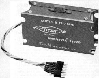
No accuracy or performance is lost with variable inductance.
Output is linear and has 3/4 in. total travel. Easily mounted.
Variable inductance is accomplished by moving a bar of
iron (a length of 4-40 steel bolt) inside the bobbin of
the tightly wound coil on the left. This bar screws into
the output arm of the servo and its position is adjustable
for servo centering.
|
Design and development of a new kind of feedback servo. An important
article for the well-informed enthusiast and the scientifically
inclined reader.
Feedback control systems, either digital or analog, must utilize
some form of feedback component to provide the appropriate reference
signal denoting servo output position. Radio control systems have
characteristically used the potentiometer as the feedback component,
either in the form of a linear wire-wound element or a circular
fired ceramic element contacted by wipers. They are subject to performance
deterioration caused by vibration, dirt and oxidation, which interrupts
contact between the wiper and the element or to more drastic failures
caused by breakage of the wire wound or ceramic element. The desirability
of replacing the potentiometer with a feedback component which requires
no phy-sical contact has long been unquestioned; however, the implementation
of other techniques has not been fruitful until recently.
Our initial attempts to eliminate the pot problems were directed
toward improving it as the feedback element. During this investigation
it was found that most of the wear in the pot was not caused by
actual control movements but instead was located in a very narrow
band around the center position of the servo as the result of control
surface flutter being transmitted to the servo assembly through
the pushrod. In general, in a system in which the servos have not
been periodically rotated between control functions, the R, E, and
A servos show markedly greater pot wear than does the throttle servo
pot.
Samples of all available commercial potentiometers were procured
and evaluated for application to feedback servos. We found that
some were unsatisfactory for reasons of: 1) Size, 2) Susceptibility
to wear, 3) Operating torque, 4) Ease of breakage, and 5) Exposure
of wipers to foreign matter. Of the types evaluated, the fired ceramic
type with a sealed housing was found best. However, it was felt
that the feedback technique still required further improvement.
Design Goals. The requirement for any replacement
for the conventional feedback potentiometer was established to be:
a) No wiping contacts; b) As economical as the potentiometer; c)
No more complex than the conventional servo; d) Easy alignment and
adjustment; e) Easily manufactured, including ready availability
of components; f) Weight and volume not to be compromised. Alternative
Approaches. Electronically, the conventional feedback potentiometer
is used as a voltage divider. A fixed voltage is applied across
the pot and the wiper serves to establish reference voltage as it
moves along the element. Arrangement is such that the voltage appearing
on the wiper is directly proportional to the position of the servo
output arm. In the digital system this voltage is used to govern
the duration of a reference pulse generated for comparison with
the incoming control pulse and the reference pulse is made to be
directly proportional to the actual position of the servo output.
The first approach undertaken was a modification to existing
circuitry using a variable capacitor in the monostable multivibrator
used to generate the reference pulse. A single-shot, or mono-stable
multivibrator, exhibits a pulse duration which is determined by
a capacitor-resistor time constant. From a theoretical viewpoint,
it is possible to change this time duration by changing the value
of either the capacitor or resistor; however, this approach was
discarded in favor of using a new design approach which utilizes
an induction as the variable component in the reference generator.
|
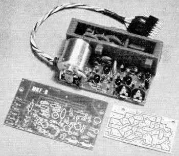
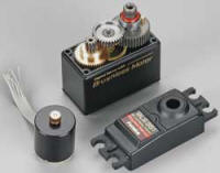
Servo under construction shows the kit's two etched and
printed PC boards whose parts are widely separated for easy
assembly.
The gear train gives lots of power and speed, three pounds
thrust and 0.6 sec. end-to-end movement. A durable and rugged
assembly.
|
The next approach involved using a variable inductor in a conventional
single-shot. An inductor-resistor also represents a time-constant
circuit. It is not practical to substitute a variable inductor directly
in a conventional single-shot reference generator because approximately
0.2 henrys of inductance is required. In our application this means
that the inductor would weigh at least 4 or 5 ounces, which would,
of course, be prohibitive.
We next examined the use of light intensity as the variable.
This system could be implemented by using a standard light bulb
for a light source and using a photodiode or photoresistor as a
detector of this light. By placing a sliding screen between the
source and the detector and making the screen such that its transparency
is a function of the position of the screen, one could achieve an
appropriate reference parameter in or at the detector which would
be directly proportional to the position of the screen sliding between
the light source and the light detector. The author had done some
previous work with this type system and found it to be most successful.
This type technique would satisfy a great majority of the requirements
established for the servo feedback element; however, it was determined
that there were four deficiencies which made the technique impractical:
a) Limited bulb life and catastrophic failure with no warning; b)
Poor vibrational environmental characteristics; c) Excessive battery
drain required to drive the light source; d) Impractically expensive.
Aircraft AC autopilots commonly use an inductor known as the
linear variable differential transformer as the feedback component.
Some basic experimentation proved this to be impractical in our
application. The differential transformer required is large and
has multiple windings, is difficult to produce or procure.
Design of Preferred Alternative. It was concluded
that any further attempt to use inductive or capacitive feedback
would have to involve new reference circuitry instead of the conventional
single-shot reference generator and, further, that they could not
be used in their conventional timing sense.
It is required that the digital servo operate on a delay on the
order of one millisecond because the FCC regulations limit the band
width of our equipment. Any further decrease in the delay means
that the limit would be exceeded.
The use of a variable inductor in a new timing circuit was investigated
next and proved to be an acceptable approach. It seemed reasonable
that one could use the reverse induced EMF which appears across
an inductor when the current in the inductor is changed. Going back
to basic electronics, you will recall that if a steady state DC
current is established in an inductor, and then is interrupted,
or turned off, a voltage is induced across the terminals of the
inductor. The magnitude of this voltage is a function of the magnitude
of the current which was being passed through the inductor and the
speed with which the current was turned off. It is also a function
of the actual inductances of the coil itself. The formula for this
induced EMF is E = L di/dt. Because the inductance is a function
of the permeability of the magnetic flux path, it is quite simple
to change the inductance of a given coil by moving an iron core
in and out of the coil.
For example, this same mechanism is used in the RF coils which are
used to tune the receiver in radio control systems. Visualize an
inductor wound on a straight hollow form with an iron core moving
in and out of the coil and you have an inductor whose value of L
is dependent upon the position of the core in the coil. In the servo
application, this core could be rigidly attached to the moving output
arm of the servo while the coil would be fixed to the stationary
portions of the servo. Hence, the position of the core would be
determined by the position of the servo output, hence the value
of inductance would be proportional to the position of the servo.
By passing a fixed DC current through the inductor, and then turning
it off abruptly, a voltage would be induced across the terminals
of the inductor with the magnitude of the voltage proportional to
the position of the servo. By properly designing the electronic
circuitry, we produce a voltage proportional to servo position and
achieve a feedback element which does not require wiping contacts.
The problem remaining is to generate, from this induced voltage,
the time delay approximately of 1 millisecond and, at the same time,
maintain a direct relationship between the magnitude of the induced
voltage and the duration of the time delay.
Mechanization of the preceding approach has been successfully
achieved in the Titan Magnevac servo. In order to discuss this mechanization,
refer to the schematic. The general functions of the different portions
of the circuitry are as follows: Q1 is an input buffer and amplifier.
Transistors Q2, Q3, Q4 with the variable inductor, L1, and associated
resistors and capacitors, form the reference pulse generator. Diodes
D70 and D71 form the comparator gate for one direction of servo
travel, and D50 and D51 and resistor R52 form the comparator gate
for the other direction of travel. Q5 amplifies and inverts the
output from the latter half of the comparator.
Transistors Q7, Q9, Q11 and Q13 form a pulse-stretching network
and the driver transistor which causes the motor to run in one direction
and transistors Q6, Q8, Q1O, and Q12 produce the opposite direction
of travel.
Let us now investigate the operation of transistors Q2, Q3, and
Q4. The inductor L1, is the feedback element and is located in the
emitter leg of transistor Q2. Resistor R20 (4.7K on the base of
Q2) biases Q2 ON so that, in the normal quiescent state, transistor
Q2 is conducting and draws a steady state DC current of about 3
milliamperes through inductor L1. Q3 and Q4 are cross coupled in
the basic Schmidt trigger configuration with transistor Q3 biased
ON and Q4 biased OFF. The collector of transistor Q3 is the output
of the reference generator and is coupled into both comparator gates.
With Q3 biased normally ON, the output, or collector of Q3, is at
or near ground potential.
The reference generator is triggered once each frame by the command
pulse routed to each servo via the yellow lead of connector P1.
This is a positive going signal whose duration (width) specifies
commanded servo position and is the one millisecond duration mentioned
earlier. This pulse turns on transistor Q1, thereby generating a
negative going pulse with a duration of 1 millisecond on the collector
of Q1. The rise and fall of this negative going pulse is differentiated
by C20 and R22 to form first a short negative going spike, and then
a short positive going spike 1 millisecond later. The negative going
spike is coupled through diode D20 to the base of Q2 and turns Q2
OFF i.e., causes it to stop conducting.
This means that the current has abruptly ceased to flow through
inductor L1 and a reverse voltage is induced across L1. Thus, the
top of L1 (the emitter of Q2) is caused to go negative for a short
duration. The magnitude of this induced voltage is dependent upon
the position of the core in the inductor L1. When the servo is at
one end of its travel and the core is only slightly projecting into
the coil of L1, this induced voltage is in the order of minus 20
or 30 millivolts. However, at the other end of its travel, when
the core is projecting entirely through the coil of L1, the magnitude
of this voltage is as much as minus 200 millivolts. This negative
going voltage peak is coupled through diode D21 into capacitor C30,
and, because of the low resistance of the inductor L1 and low forward
resistance across diode D21, capacitor C30 is caused to discharge
abruptly. When the voltage decays across L1 and the emitter returns
to its DC level, diode D21 becomes reverse biased.
The positive going time constant (decay time) for capacitor C30
is determined primarily by the resistance value of trimming potentiometer
R34. This causes capacitor C30 to recharge toward 6 volts with a
time constant which is determined by C30 and (primarily) R34. The
fact that the junction between C30 and R34 has abruptly become a
negative voltage has caused Q3 to be turned off, thereby causing
its collector to go positive. This action causes Q4 to be turned
on.
The base of Q3 now recharges toward 6 volts until Q3 is again
caused to conduct, and through the Schmidt trigger action, Q3 quickly
turns back on thus turning Q4 off. One cycle of operation of the
reference generator in now complete and the output, or collector
of Q3 has changed state for a period of approximately 1 millisecond.
As the core is moved further into inductor L1, the negative induced
voltage becomes greater, thereby causing capacitor C30 to be further
discharged. Since capacitor C30 recharges at a constant slope, it
can be seen that for larger negative voltages, we generate a longer
time delay during which transistor Q3 is off. This is the basic
mode of operation of the Magnevac timing circuitry. A U.S. patent
is pending on the circuitry around Q2, Q3, and Q4 and should be
granted very shortly.
The remaining circuitry of the servo is more or less conventional.
Position of the servo is a function of the input pulse width. The
reference pulse is compared to the input pulse, and the appropriate
pulse stretching and driver chain is turned on depending on whether
the commanded pulse is wider or narrower than the reference pulse.
This process is repeated once each pulse repetition period until
the widths of the reference and commanded pulses coincide to produce
a nulled condition.
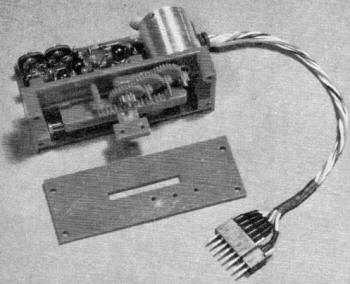
A photograph shows the mechanical arrangement of the inductor
and the core. Notice that the inductor itself is a coil-form which
is attached rigidly to the printed circuit board of the servo. The
core that moves in and out of the inductor is a soft steel continuous
threaded 4-40 rod with a screw driver slot in one end for adjustment.
The slug threads into the post which is an integral part of the
output rack. When the rack or output arm of the servo moves, the
slug moves with it, in and out of the inductor. The center position
of the servo is readily adjusted by screwing the core into or out
of the post. If this adjustment is performed with a nonferrous screw
driver, the position of the servo can be adjusted for proper centering
while the servo is operating. The resolution of this adjustment
is exact.
Servo Development. Referring again to the schematic
you notice that both R21 and R34 are potentiometers which provide
for adjustment. R21 adjusts the DC current which flows through the
inductor to change the absolute magnitude of the voltage induced
across L1 when transistor Q2 is turned off. R34 controls the recharging
time for capacitor C30. Thus, adjustment of R34 changes the slope
with which C30 recharges toward 6 volts. Hence, it is possible to
adjust both the end and the center positions of servo travel.
Extensive testing has established that the linearity of the inductive
feedback principle is better than one-half percent as measured against
the theoretical straight line. Linearity is lacking only at the
extreme ends of the coil-form. This is due to the fringing effect
of the magnetic field at the ends of the coil. However, since servo
travel is restricted to 3/4 in. and the coil is a full one in. long,
the fringing, or end effect, is not observed in normal operation.
The final version of the Titan Servo was designed to provide
a full 3/4 in. permissible travel on the output arm and a transit
time of about 0.6 seconds end-to-end. The thrust is 3 1/2 pounds.
The case is made of 0.032" half hard aluminum anodized blue and
is mountable on three sides. The case has proved to be extremely
durable and most resistant to crash damage. The size of the Titan
Servo is 1 1/16" thick by 1 3/4" high by 3 1/4" long including mounting
lugs.
The variable inductance servo is available in a wide range of
models for use with most major brands of digital equipment today.

Schematic from Titan Servo Kit.
Posted June 9, 2014
|