|
This is part two of a control line B-24 Liberator
article that appeared in two 1954 issues of Air Trails magazine. Part one covered construction
of the model and had the framework plans. Part two, here has plans and instructions for adding lots
of good detail to the model if so desired. Paint, special markings, guns and turrets, pilot, and airframe
and cockpit drawings make the job easier. It is hard to believe that as I write this, the article was
published nearly 60 years ago!
Adding Scale Detail to Your B-24 Bomber Flying Scale Model
By Frank Lashek and Cal Smith
Part II presented here covers scale details and markings to complete model. Part 1 in the
August 1954 issue dealt with construction.
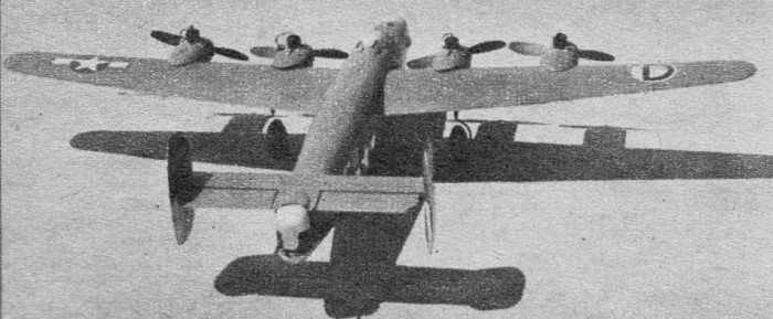
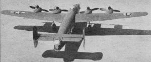
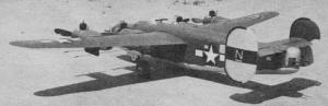
Real-life "Liberator" (with bomb bay door in opened position) was War Bond stimulus.
With all woodwork complete the model is now ready for finishing. Depending upon amount of work the
builder wishes to undertake, plastic enclosures should be tackled next. Turrets, bombardier's window,
astrodome, cockpit canopy and all side windows are clear plastic. You may wish to make up wood patterns
and mold each of these items or you may wish merely to simulate these enclosures with carved blocks
painted aluminum color. All side windows can be made from flat sheet plastic inlaid flush with skin.
Many scale model builders prefer ignition engine power because a fuel-proof finish is not required.
This really simplifies finishing such a large model as this B-24 since regular nitrate dopes can be
used. If on the other hand you wish to use glow-plug engines, fuel-proof dopes should be used throughout.
You might take a chance on fuel proofing nacelles only to make the job easier. Whatever power you use
will of course determine the kind of dopes required. The instructions which follow here apply to either
method of finishing.
Clear-dope all wood surfaces and sand smooth. Dope on light-weight Silkspan over entire model. Add
two more coats of clear dope over paper and sand smooth. Now add bombardier's window, cockpit canopy
and flat side windows. Turrets and astrodome can be added later. Mask off plastic areas and spray or
brush several coats of Duco Auto primer over entire model. Use fuel-proof primer if this type finish
is being applied. Wet-sand primer and apply more coats if needed to make smooth surface.
Use Testor's Olive Drab if finishing with regular dopes. Gray color is about halfway between Aircraft
Gray and Battleship Gray. We found no fuel-proof olive drab available, so mix Aero-Gloss Medium Green
with Orange to get olive drab. Start by adding small quantities of orange to green and compare with
Testor's olive drab, only a little orange at a time until color comes close. Aero-Gloss Cessna Gray
should be darkened a little for proper color.
Apply final coats of colored finish to model on areas as follows:
Entire lower surface of wing is gray, bottom of nacelles are gray to wavy line shown on plans. Belly
of fuselage is gray up to wavy line shown. Lower surface of stabilizer and elevators are gray. Inboard
side of fins and rudders are gray up to horizontal tail.
Entire top surface of model is olive drab including inboard side of vertical tails above horizontal
tail. De-icer boots on leading edges of all flying surfaces are black as indicated on the plans.
Since finish on real airplane was very dull, there is no need to rub down the model finish. Scale
judges please note! Both regular and fuel-proof dopes do not have dull scale-like quality desired, but
a smooth unpolished finish will approximate the type of finish used on the real airplane.
Some versions of B-24 were not painted but left natural aluminum color. You may prefer this paint
job rather than camouflage olive drab and gray.
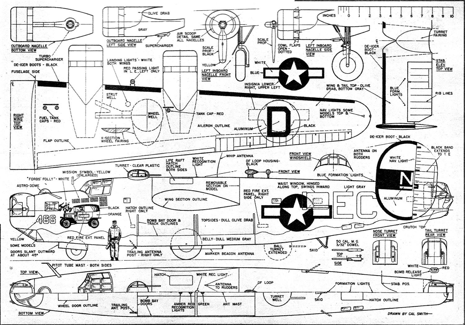
The distinctive markings and name used on the model are taken directly from one of the airplanes
crewed by Sgt. Frank Lashek while he was serving with the 8th Air Force in England during World War
II. The details are based on a large album of photos made by Lashek while on duty at the home field
of the airplane in England.
Starting at the nose, these markings include the following: a 5/8" high N centered just below nose
turret and above bombardier's window. N is silver with bar below as on fin. Numeral 466 in yellow carried
on both sides of fuselage. "Ford's Folly" in white on both sides of fuselage. Cartoon "tin lizzy" carried
on left side only had orange body, black top, tires and fenders, brass colored radiator and hub caps.
Mission symbols in shape of bombs were yellow, arranged in groups of five on left side only. "Ford's
Folly" carried 46 at the end of her tour.
Farther aft along fuselage standard blue and white insignia were carried. Note: no red strips in
bars. Large EC light gray or dirty white carried on both sides of fuselage. Outboard surfaces of both
vertical tails were aluminum color with black band from leading to trailing edge at center. Letter N
with bar below was also aluminum color.
Wings carried standard insignia on upper left and lower right tips. Large black D on aluminum circle
carried on right wing top only.
B-24 control line model nose and cockpit detail.
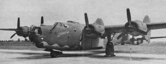
Other airplanes based at same field with all-over natural aluminum finish carried similar markings.
A dark green anti-glare panel was painted on fuselage top ahead of windshield extending to front side
of astrodome. Bottom edge of point was on line with bottom edge of cockpit side window.
Typical examples of markings are: Small black H on nose, black numeral 293 on nose side. Black EC
aft and silver H in black band on tails. Large D on white circle on right wing. Another example is same
as above except numeral is 636 on nose, and letter B with bar above on nose and tails.
There are many other spots of color shown on drawing. These are self-explanatory and include: red
fire extinguisher panels on left front and right waist. Recognition lights top and bottom, blue formation
lights on top fuselage and stab. Fuel tank caps are red on wing top. Bomb release light, half white,
half red below tail turret. And of course the navigation lights, red on left, green on right wing top
and white on fin sides.
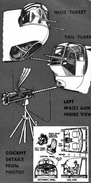
The many scale details on the model can be simulated in various ways depending on how much work the
builder wishes to undertake. Here are some suggestions as to how this can be accomplished. Sketches
are included of nose and tail turrets. They will give an indication of plastic and metal areas; note
ribs running fore and aft. Rear turret has flat bullet-proof glass panel in center with area around
guns open. Top turret is all plastic with slot from bottom up to center line for gun movement. The ball
turret in after belly was retractable for landing and take-off. It is suggested it be left "up" on the
model. The belly has a large cut-out for ball and guns.
Sketch of waist gun shows tubing tripod and link cartridge belt coming down from overhead. Note recoil
damper tubes on side, twin handles and trigger housing on rear. This is added over detail on drawing
of standard gun on plans. Waist windows can be left closed so that only small plastic area in center
shows, or large opening can be cut in side with guns in position inside.
Pitot tube masts or booms on nose can be cut from hardwood or sheet brass. Trailing antenna post
can be 1/16" dia. dowel or brass rod with small bean in end. Marker beacon antenna on belly has two
short masts, these can be hardwood. Whip antenna on fuselage top can be a length of .015" or .020" wire.
DF loop housing can be carved from hard balsa or soft pine. Formation lights and navigation lights project
slightly, so could be made from small beads imbedded halfway into skin.
Rib stitching at rib lines on all movable control surfaces can be simulated by cementing lengths
of thread to wood surface.
Underside of wing has large fairing behind wheel well. This can be carved from block balsa.
Detail on nacelles includes the exhaust pipe and turbo-supercharger on bottom. Carve from hard balsa
or pine. The exhaust pipe is round from cowl flaps back to tapered section. This section is flattened
but still oval in section. The turbo-wheel housing has rounded edges and waste gate stack is round.
The skin of nacelle bottom can be cut out for this assembly. Superchargers are the same on all engines,
except that on outboard engines exhaust pipe section is a bit shorter.
Cowl flaps on nacelle top and bottom can simply be drawn on surface as if in closed position. Note
shallow indentation along rear edge of flaps. This extends along top and bottom only, with side areas
smooth.
Model main landing gear strut wire is formed to match scale strut shape. Gear outlines can be simulated
with brass tubing over the wire. Brace strut forward and retracting strut sideways can be dummied with
tubing, but ends should float in nacelle and wing to allow for landing load deflections. Strut cover
door on inboard side of gear can be tin-can stock soldered in place.
This about completes the gadget review. There is lots of hard work finishing up the many details,
but the pay-off will come at the contests. Any model finished up with all these extras will really be
a show stopper and a prizewinner.
Fly on 50 or 60 ft. length of .021 wire. Be sure model balances as shown. Add ballast to nose or
tail as needed.
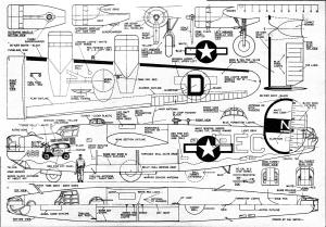
Scale Detail Plans for B-24 Liberator
Posted April 25, 2015
|