 Table
of Contents] Table
of Contents]People
old and young enjoy waxing nostalgic about and learning some of the history
of early electronics. Popular Electronics was published from October 1954 through April 1985. All copyrights (if any) are
hereby acknowledged.
See Popular Electronics articles
on aircraft modeling. See all articles from
Popular Electronics. |
I purchased a couple batches of vintage Popular
Electronics magazines off of eBay for use on my engineering website, RF Cafe; however, upon scanning through the pages I was pleasantly surprised to
find that many articles on radio controlled airplanes were included. The 1950s and 1960s were relatively
early in the R/C sport, and such things were still considered a novelty. Of course, today the toy shelves
of even Walmart are full of R/C products. Kids today take them for granted... as I suppose my generation
took for granted Erector Sets
and Lincoln Logs.
Anyway, I have begun scanning and OCRing (Optical Character Recognition) some of the articles and
posting them here on AirplanesAndRockets.com.
This first one, from the December 1954 edition, was written by none other than Bill Winter. Bill
was the editor for American Modeler
and American Aircraft Modeler, and Model Airplane
News for many years.
See complete list of Popular Electronics
articles on aircraft modeling.
Flying the R/C Plane
So you've built a model plane for radio control-will it fly true and handle easily? This is how
you find out.
By William Winter
 OF
THE many important factors involved in successful radio control flying, none is more important than
the airplane and the builder's ability to balance and adjust the model (i.e., trim) and fly it properly.
A good airplane is as necessary as a good transmitter or receiver; good flying technique as important
as ability to tune the electronic equipment. Much has been said about radios. Let's, for a change, take
a close look at the plane. OF
THE many important factors involved in successful radio control flying, none is more important than
the airplane and the builder's ability to balance and adjust the model (i.e., trim) and fly it properly.
A good airplane is as necessary as a good transmitter or receiver; good flying technique as important
as ability to tune the electronic equipment. Much has been said about radios. Let's, for a change, take
a close look at the plane.
It is not necessary to be an aerodynamicist, or to bone up on aero text books. But let's face it
- an understanding of what makes an airplane stable and controllable is as necessary as knowing plus
from minus. For the first time in a magazine of this type, we will outline these "trade secrets" in
as painless a manner as possible.
In this enlightened air age it is well known that an airplane's wing lifts because of the partial
vacuum created above its curved upper surface as the craft travels forward through the air. More properly
put, there is a pressure differential between the air over the wing and the air under it, with the result
that the wing tends to lift, or move upward. It is also widely understood that the lift offsets the
weight of the machine, and that the thrust of the propeller offsets the resistance (drag) of the plane
created by its forward passage through the air.
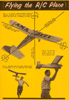
An airplane has movement about three axes (see Fig. 1): one is the longitudinal axis (fore and aft)
similar to the barbecue spit, around which the plane rolls; two is the directional axis, like the pivot
in a weathervane, around which the plane turns; three is the spanwise axis, like the fulcrum of a child's
seesaw, around which the plane noses up or down.
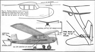
The plane is kept stable, or level, about these three axes, by certain arrangements of its surfaces.
See Fig. 4. The dihedral angle, or upward tilt of the wings, is primarily responsible for the plane's
resistance to rolling and spiraling into the ground. Therefore, do not depart from the kit maker's plans
and specifications.
Stability about the directional axis is governed by the proper size of the vertical fin; stability
on the fore-and-aft axis is achieved by the placement of the wing relative to the center of gravity
(CG), or balance point of the machine, and the placement and area of the horizontal tail surface. This
is perhaps an oversimplification, but it serves our purpose adequately.
Directional and lateral (rolling) stability does not concern us here because, if the plane is accurately
built from a kit, carefully lined up, and free of warps (warps, incidentally, are taboo, as they make
the plane ungovernable) it is automatically stable in these two respects.
Our big concern is the spanwise axis (the business of the seesaw). Consider that the lift of the
wing, if placed forward of the center of gravity, would tilt upward its end of the seesaw (the nose)
if not counter-balanced by some other force. This balancing force is provided by the lifting action
of the stabilizer, or horizontal tail. Thus, the greater force of the lifting wing, acting through a
small distance or moment arm, about the center of gravity, is offset by the smaller lift of the horizontal
tail acting through a greater distance.
 Let's assume that the plane is tail heavy - the nose tends
to rise toward the point at which normal air flow over the wing breaks down with sudden loss of lift
resulting in a stall. Our seesaw can be restored to balance in several ways. The lifting force of the
wing may be decreased by slightly reducing the angle at which the wing meets the air, the wing may be
moved back slightly (reducing its moment arm), the center of gravity may be moved forward with the same
effect; or, tackling the problem from the other end, the lift of the stabilizer may be increased by
adding to the angle at which it meets the air stream.
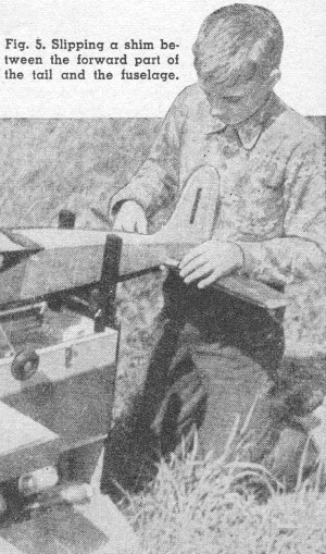
Naturally, all of these possibilities may not be available - if the wing rests upon a cabin top,
it can hardly be moved forward or backward, but changes in CG position may be made by relocating heavy
bat-teries, and the angle of either wing or tail may be altered by thin shims, such as thin balsa wood,
matchbook covers, etc., placed between the wing or tail and the fuselage. In Fig. 5, a shim is shown
being inserted between the tail and fuselage. Permanent shims may be cemented in place after adjustments
have been made. Of course, if the plane is nose heavy, tending to dive, the corrective measures are
reversed. So much for aerodynamics.
Before launching into the actual trimming and adjusting of that new model, it would be wise to explain
one very important stability factor which even model plane fans very often do not appreciate. Regardless
of changes and adjustments to the plane's surfaces, always maintain a slight angular difference between
the setting of the wing and stabilizer. The wing should be set at a slightly greater positive angle
of incidence, at least one degree, but not more than 3 degrees greater than that of the tail (work this
out to a fractional part of an inch to facilitate measuring).
 Because the tail works at a lesser angle, it will reach the stalling
point after the wing has stalled, continuing to lift, and will always exert an increasing leverage as
the plane noses up, to restore it to level flight. Should the tail be set at the greater angle, or sometimes
even at the same angle, the plane will stall more severely and completely (because the stabilizing effects
of the tail suddenly vanish whim it stalls). Moreover, at high speeds, as in a dive or spiral, the extra
lift from the tail may overbalance the seesaw and put the ship into a death dive from which recovery
is impossible. Many modelers forget this when they balance a tail-heavy plane by excessively increasing
the positive angle of the stabilizer - within reason it is safe to so adjust the stabilizer, but never
forget the need for angular difference. Because the tail works at a lesser angle, it will reach the stalling
point after the wing has stalled, continuing to lift, and will always exert an increasing leverage as
the plane noses up, to restore it to level flight. Should the tail be set at the greater angle, or sometimes
even at the same angle, the plane will stall more severely and completely (because the stabilizing effects
of the tail suddenly vanish whim it stalls). Moreover, at high speeds, as in a dive or spiral, the extra
lift from the tail may overbalance the seesaw and put the ship into a death dive from which recovery
is impossible. Many modelers forget this when they balance a tail-heavy plane by excessively increasing
the positive angle of the stabilizer - within reason it is safe to so adjust the stabilizer, but never
forget the need for angular difference.
The Hand Glide
The first test for any new plane is the hand glide. Perform this test in calm weather or in the slightest
possible breeze. Remove the propeller to avoid breakage. If the model is a simple one with simple equipment,
it is safe to leave the radio and associated equipment in place. If it is a complicated job with vulnerable,
heavy radio, simply remove the radio provided it is located close to the center of gravity of the plane;
otherwise replace it with an equal weight.
Pick a grassy area where landings and bumps will be cushioned. Hold the ship two or three inches
behind the CG position, level it with the nose pointing at the hori-zon (see Fig. 3), and run slowly
without releasing the plane. Repeat this times, running faster arid faster, until you can feel the point
at which lift is exerted as shown in Fig. 2. Now point the nose of the plane slightly below the horizon,
at a spot about 50 feet away. Run at the same speed as before, and as you release the plane, impart
the very slightest push. You may have to repeat this step a few times to approximate the gliding speed
of the ship.
Never throw the plane; unless it is very heavy, as it will rear upward, irrespective of trim, to
stall and 'then dive into the ground. It is better to launch the ship too slowly at first which, in
grass, means a hard landing at the worst.
Observe closely the manner in which the plane glides. Is the plane tail heavy (stalls) or nose heavy
(dives)? Usually, all such tendencies can be ironed out by increasing or decreasing, respectively, the
angle of incidence of the stabilizer; if not, the CG position should also be altered, forward if tail
heavy; backward, if nose heavy. When the plane glides correctly, it should follow a straight flight
path from the hand until it lands two-points upon the wheels. It should not float or appear to hover
or describe a pretty arc toward the ground, whereby the plane seems to flare out nicely for a three-point
landing. This looks good, but the plane would stall badly in flight, especially with the engine running.
You want a fairly fast and flat glide. If there is a breeze, the model should evidence "penetration,"
boring straight ahead to a landing and not be buffeted aside by the wind. If the glide path curves to
right or left, adjust the rudder slightly to remove the circling tendency but be sure that a warp isn't
present in the wing, stabilizer, or fin, and that all the surfaces are accurately lined up. If the wing
is slightly askew it will make the plane turn. If one tip is higher than the other, or one stabilizer
tip higher than the other, the results will be the same.
Now that we've gone through all the motions of the first trial glide, we will have to check the plane
on powered flight. Of course, if the model is a glider, you will merely repeat the hand launched glide
tests until the ship is completely checked out and then, you're ready for a glide aloft. Next month,
the first power-on test flight will be discussed, and many of the points mentioned will apply equally
Well to the glider, which uses the same type of flight controls as the gas model. END
Posted July 3, 2011
Vintage Popular Electronics Magazine Articles
- R/C Notes, January
1956
- R/C Triplex: Three Controls on One Channel,
November 1956
- R/C Reliability,
March 1955 Popular Electronics
-
Robot Helicopter, November 1956
-
Model Boat for the 27 mc. Citizens Band , March 1953 Radio & Television News
- Adjusting
the Power - R/C Plane, January 1955
- Rejuvenate
R/C Batteries, July 1955
- 3 and 4 Finger
R/C Escapements, January 1955
- Radio Control
of Models, October 1954
- The R/C Cloud, February 1960
- Radio
Control Installations, February 1955
-
Compound
Escapements & Servos, February 1955
- Flying the R/C
Plane, December 1954
- The Lorenz
Transmitter, December 1954
|