|
March 1955 Popular Electronics
 Table
of Contents Table
of Contents
Wax nostalgic about and learn from the history of early electronics. See articles
from
Popular Electronics,
published October 1954 - April 1985. All copyrights are hereby acknowledged.
|
The topic of R/C system
reliability rarely is mentioned in model airplane magazines these days. Many of
the high-end, big dollar planes like jets (turbines), giant scale and giant 3D,
do use redundant receivers and batteries because the pilots have thousands of
dollars worth of equipment and hundreds of hours of personal time invested in
them. Operating at 2.4 GHz with spread spectrum modulation, there is little to
no chance of radio interference, which was a huge problem back when this article
appeared in a 1955 issue of Popular Electronics magazine. William
("Bill") Winter, who would later serve as president of the
Academy of Model aeronautics (AMA),
was editor of Model Airplane
News magazine at the time. Vacuum tube receivers and electromechanical
escapements and relays were being used in model airplanes. The very nature of
construction of those components made them extremely vulnerable to vibration and
shock induced intermittent or total failures. The models themselves were
necessarily large and often underpowered for carrying such heavy loads aloft. We
owe the R/C pioneers a lot for taking the arrows of trial and error to
ultimately give us the carefree systems we enjoy today.
R/C Reliability
 By William Winter By William Winter
Editor. "Model Airplane News
Radio control of your model airplane gives you greater realism and maneuverability
in your flights but - you're inviting loss of control if you don't have reliability.
Radio control is simple. Connect the wires, turn on the switch and, presto, you're
in business. Start the motor, launch the model, turn it left, right, glide in for
a landing. Wow, this is a cinch! (Famous last words!)
Heresy? Not at all. Everybody who has flown radio-controlled models knows that
the tenth flight is harder to achieve than the first, that one deserves a medal
for making 50 hops without a slip, and 100? Well, sir, the century mark accomplished
without a crack-up or a chase of an errant plane is a test of man and equipment.
Mainly, it is a test of man.
Can he remember to check battery voltages? Clean a relay? Keep the transmitter
tuned? Watch for vibration-fatigued wires? Anyone, even the duffer, can make a few
flights, but we are talking about reliability. Good flight after good flight, not
just a "new car" type of reliability!
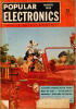
A Citizen-Ship radio control receiver operating on the 465 mc.
Citizen's band. Note the special shock mounting for the tube and the use of a Sigma
4F relay.
Sigma 4F relay for radio-control receivers. This is and has been
one of the most popular of relays for radio control model work. A new relay. the
Sigma 26F has been especially designed for R/C fans.
It goes without saying that there can be no reliability without a good, properly
tuned transmitter and a sufficiently sensitive receiver which also is properly tuned
and adjusted. If it is impossible to get very close to the maximum receiver current
drop or rise (as the case may be) upon signal, when the receiver is tuned to the
transmitter at an absolute minimum of 600 feet on the ground, it is a gamble every
time the plane is put into the air. Any lapse, even a single skip of the rudder
which cannot be clearly accounted for, should ground the plane that day. Yet at
every flying session at least one person takes such a risk.
Relays
Relay dependability is primarily a matter of the amount of current change available,
shock mounting, and proper adjustment. If large current change is available, permitting
a pull-in and drop-out adjustment at a high current reading on the meter, the result
is good contact pressure and positive armature action. The higher the power of the
engine and the flying speed of the airplane, the more critical these adjustments
become because of the increased effects of vibration.
For example, one of the author's models has a wing span of 5 1/2 feet, a gross
weight exceeding 6 1/2 pounds, and a .29 cubic inch displacement engine. The single
hard-tube Miller receiver idles at 2.8 mils, drops to one mil with signal at a distance;
the relay (Kurman 5,000 ohm) is adjusted to pull in at 2.2 mils (leaving a margin
of 0.6 mil if the idling current decreases) and drops out at 1.7 mils (leaving a
margin of 0.7 mil to allow for weaker signals at extreme range in the air). The spread
between pull-in and drop-out is 0.5 mil. In this particular airplane, a smaller gap
or difference between pull-in and drop-out is dangerous. At a 0.2 mil difference,
vibration causes the relay to actuate the escapement without a signal being given.
Of course, this is an extreme example. A difference of 0.2 mil is considered the
reliable minimum for average installations.
A current change of 1.5 mils is desirable for reliability (allowing for variations
in plane and power), although receivers can be operated with a current change of
approximately one mil with good results. Small current change, low operational currents,
and low spring tension will make contact opening and closing unreliable. Thus, the
relay may skip in the presence of vibration, as when spiraling the model down, where
a miss could mean a cartwheel contact with the earth. Arcing (the sparking at the
relay contacts when the flow of current to the actuator is broken) must be suppressed.
Otherwise, over a period of time, the contacts may become pitted and dirty, producing
sticking of the armature (spin to earth), or lack of electrical contact (ship flies
off). A .02 μfd. disc ceramic capacitor and a 1/2. ohm, 10 watt resistor in series
across the relay contacts (from armature contact to live contact) will suppress
this arcing.
Probably the lowest relay operational values in general use are found with the
single gas-tube receivers and the 465 mc. hard-tube jobs. In the gas-tube Aerotrol,
for instance, the tube normally would idle at 1.3-1.5 mils, dropping at a distance
with signal to perhaps .3 mil. The relay should not be set with too great a difference
between pull-in and drop-out, otherwise the available margin above and below this
range would not be adequate for safety. Also, relay armature action would be fluttering
and unreliable.
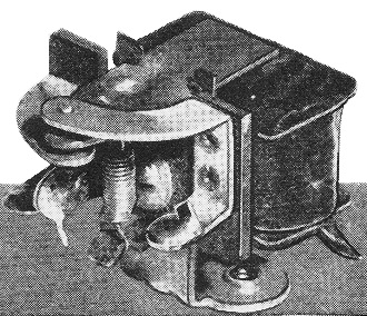
The Kurman relay shown here has been used in thousands of R/C
iobs. The new Kurman relay has adjustable screw contact points.

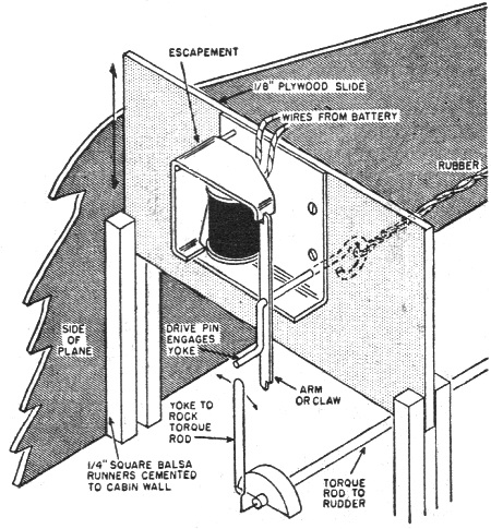
For ease of inspection and maintenance of the escapement, mount
it on a slide that can be taken out of the plane, as shown here. A drop of cement
will hold the slide in its grooves in the plane during flights.
Indeed, most gas-tube receivers operate a relay with a 0.2 mil change between
drop-out and pull-in, for example: 1.1 mils pull-in if the idle current is 1.3 mils,
with a 0.9 mil drop-out. Two tenths mil idle above pull-in is regarded as minimum.
The greater margin between drop-out and signal-on current is to allow for diminishing
signal as the airplane flies out. If drop-out was, say, 0.6 mil and, at 1,500
feet distance, the signal-on current drop reached only 0.61 mil, no contact
could be made and the plane would be on its own, unless it circled closer to the
transmitter. At the other end, any drop in idle current (such as might result from
weakening batteries) might wash out the margin of idling current above the relay
pull-in. In the case where the idle current is 1.3 mils and the pull-in value
is 1.1 mils a fall in idling current to less than 1.1 mils, would not permit the
relay to pull in once dropped out, and the ship inevitably would pile in.
It is interesting to note that one of the practical results of lower currents
and contact pressures is the effect on the receiver and/or relay suspension. Such
receivers have to be mounted relatively loosely in the airplane to avoid vibration
effects, whereas receivers having higher operating values and current changes can
be more firmly tied down. With either the single gas-tube receiver or the 465 mc.
job, a 5 1/2-foot plane, such as the Live Wire Sr., should not be powered by more
than a .19 engine for trouble-free operation by the average modeler. In a small
plane like an .09 powered Live Wire Trainer, vibration would not be a problem.
Some hard-tube receivers idle at 3, 4, or even 4 1/2 mils. It is to be realized,
however, that higher idling currents are rough on batteries, so much so, that hearing
aid "B" batteries cannot be used reliably with such receivers - unless it is convenient
to swap batteries after every flying session.
One drawback of the one-tube receivers commonly used is that the single tube
must perform both detection and amplification. This problem can be avoided by the
use of a multi-tube receiver. In the Babcock single-channel tone receiver, the third
or final tube (the relay tube) comes through with a fantastic wallop of some 6 mils
current change.
In the Lorenz type of two-tube receiver, the first tube may be idled at anywhere
from 0.4 to 0.7 mil (depending on the particular receiver), dropping to a fraction
of a tenth of a mil at a distance. This drop is accompanied by a current rise of
as much as three mils in the second or relay tube, depending on the batteries, relay
resistance, and values of limiting resistors and potentiometer. Since the second
tube is idling at virtually nothing before signal, the current change through the
relay is practically three mils. The relay can be adjusted for say, a one mil change
between pull-in and drop-out. The slamming action of the armature is audible outside
the airplane and the contact pressure is excellent, holding on through the roughest
vibration. In small airplanes, many builders fasten the relays down without shock-mounting,
although, for reliability, the author favors shock-mounting everything. Not only
relays, but tubes also can have their wits addled by a rough engine.
A relay that closes the actuator circuit upon pull-in is more reliable than one
that functions on drop-out because the contact pressure is higher. On pull-in the
magnet maintains armature pressure against the contact, but on drop-out only spring
tension maintains contact.
This is not a relay article, and the adjustment of various types of relays is
not our business here, but a few tips may help. Do not allow the armature of the
relay to come into contact with the core piece or magnet; otherwise, residual magnetism
may build up in the armature and cause it to stick on making contact. Put a piece
of cigarette Cellophane over the core piece, pressed flatly in place with the ends
neatly cemented down. Since a very slight air gap normally is left between the armature
(in the pulled-in position) and core piece, this Cellophane automatically insures
that gap and prevents physical contact between armature and core piece. Now, and
this is important, be sure, in the case of receivers which operate on pull-in, that
the armature strikes the live or upper contact before it touches the Cellophane
or core piece. If it does not, no contact will result, or the contact may be so
weak that vibration will cause the armature to flutter, making and breaking contact
and wiggling the rudder.
In the Sigma 4F type of relay, always check the relay carefully after any crack-up,
inasmuch as the coil mounting bracket may bend or shift, or the armature may be
bent, permitting a corner to touch the core piece unobserved. Also, the frame may
be so sprung that the delicately pivoted armature will have a binding action. On
the old model Kurman relay, solder a stiff wire reinforcement along the contact
arms to prevent their shaking in resonance to vibration.
Always be sure that the contact screws in any relay do not turn easily, for vibration
will alter the relay adjustment. Clean relay contacts before every flying session.
Slide a dollar bill between the armature and live contact, place slight pressure
on the armature, and lightly polish the contacts. Some people recommend a soft brush
and carbon tetrachloride. The writer's experience has been that this method may
leave a film which prevents contact. Check the adjustment of the relay before every
flying session, after every five flights in one day, or after a rough landing is
made. A potentiometer in the plane, or mounted on the meter, allows quick variations
in current to check the pull-in and drop-out current values. Unexplained variations
in relay operational values (on some relays) may be explained by the stiffness of
the wire that connects to the moving armature, or to the shifting of the coil tension
spring where it loops over a hook on the armature or relay frame. Carefully solder
the end of such a spring to prevent such movement. Do not clean contacts with any
abrasive material because pitting will result.
Rated a close second to the relay as a trouble source is the escapement. Probably
the biggest trouble with escapements is the tendency to consider them completely
and indefinitely reliable, and then bury them in some inaccessible place in the
plane. Actually, the tension of a spring may change with long and repeated use,
or gaps and overlaps may be altered from the slamming action of the claw upon the
pawl, many thousands of times repeated. Burrs may develop on the mating surface
of the claw and the pawl, shaft holes may become elongated, dirt may get between
the armature and magnet, or glow fuel exhaust may build up an oily deposit in the
same place. The escapement should be regarded as a kind of relay for it too has
a proper pull-in and drop-out adjustment.
A thorough once-a-month check of the escapement is in order if the flier operates
every weekend. To permit such a check, the escapement must be mounted in a readily
accessible location, as on the front of the bulkhead that forms the rear of the
cabin. A large door in the floor, immediately beneath the escapement, will allow
access of fingers and tools from beneath. By far the best arrangement is to install
the escapement on a section of 1/8-inch plywood, that slides down into place between
runners of 1/4-inch balsa. By disconnecting the linkage, the escapement can be lifted,
on its mount, out into the free space of the cabin, where it can be worked upon
easily, and examined with a magnifying glass. Once a burr is seen through the glass,
inspection pays off!
Opinion is divided as to whether it is better to tape batteries together into
packs or to install them individually in battery boxes. While there is little to
choose between the pack and a good, new box, it becomes increasingly important with
use to be sure that the box maintains firm contact pressure. Sometimes, a finger
placed on the batteries in a box while the engine is running will give a stinging
sensation, showing the fantastic amount of shaking that takes place in an insecurely
boxed battery. On sensitive tone receivers, or even the typical hard-tube jobs,
the noise due to poor contacts can result in poor control. If boxes must be used,
use only those that are made expressly for radio control work.
Continuing this discussion of reliability, the author will show next month how
to check and adjust an escapement and evaluate batteries and their installation
for reliability.
Posted February 25, 2023
|