|
Here is an interesting twist on the standard balsa, plywood,
and Styrofoam model airplanes construction materials - aluminum sheet. Sheet Metal Suzie uses a .19-size
engine, has a wingspan of around 27" (~135 sq.in.), and tips the scales at 24 ounces. That works out
to a wing loading of around 25-26 oz./sq.ft., which is quite high, meaning it will have a lot of momentum
and pull on the control lines impressively. It also means 0.012" diameter braided steel lines are the
smallest you'll want to use. The author states that in order to eliminate metal-to-metal joint fatigue,
there are no metal-to-metal component junctions, which I assume he means where the metal wing attached
to the metal fuselage, because both the wing and fuselage have seams bolted or riveted to themselves.
If you decide to build Sheet Metal Suzie, I suggest you forego the 4-40 bolt option and buy an inexpensive
pop riveter from a hardware store and use it. A line of clunky nuts and bolts would really detract from
the uniqueness of the model. It should be possible to buff the metal surfaces to a high shine, then
spray a coat of clear lacquer to retain it.
Thanks to Bob Balsie for scanning the pages.
Sheet Metal Susie: All-Aluminum C/L Modelplane
By Roy L. Clough, Jr.
No hot fuel problems here; Susie's unique vibration isolation assembly means a long-lasting model
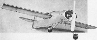 Suzie looks like a rather complex bit of sheet metal work, but
actually this gleaming aluminum beauty can be yours at a cost of so little time and effort that you
won't believe it until you try. Suzie looks like a rather complex bit of sheet metal work, but
actually this gleaming aluminum beauty can be yours at a cost of so little time and effort that you
won't believe it until you try.
The trick is the use of simple basic geometry which will distort naturally into the shape we desire.
We squeeze the ends of a cylinder and there is our fuselage; we draw together the sides of a right angle
and there is our wing section.
The main disadvantage of sheet metal models is the effect that high frequency engine vibration has
upon metal-to-metal junctures. This punishing vibration will erode or fatigue the toughest metal in
a short time. Add to this the rough shocks of repeated landings and it is easy to understand why the
operating life of metal models of the past has been brief.
Suzie was designed with the elimination of this weakness as a major point of effort. Note: There
are no direct metal-to-metal component junctures; no points where metal can chatter against metal, and
no points where heavy mass or flight loads fall upon flat, or unsupported sheet metal areas, in concentrated
fashion. Engine vibration is isolated and absorbed by a wood bulkhead which also takes landing shocks;
the wings are attached to a wooden spar as are the tail surfaces, the wood in turn being attached to
the fuselage. The result of this type of construction is a model which will still be flying years from
the time you build it-provided you don't run it into stone walls too often.
How about the weight?
We won't kid you. Suzie is fabricated from .019 aluminum sheet and this stuff isn't microfilm. She
squats on the take-off line with a full tank at 24 oz., and uses up one-third to half a circle to get
airborne with a Cub .14 - the smallest engine you should use. Once aloft, however, she flies as good
as any sport-type model with an elevator response, climb and dive, which belies its weight. When the
engine quits Suzie whistles into a high-momentum glide as flat as a table-top and keeps pulling on the
lines until she stops rolling. You'll like her.
Construction:
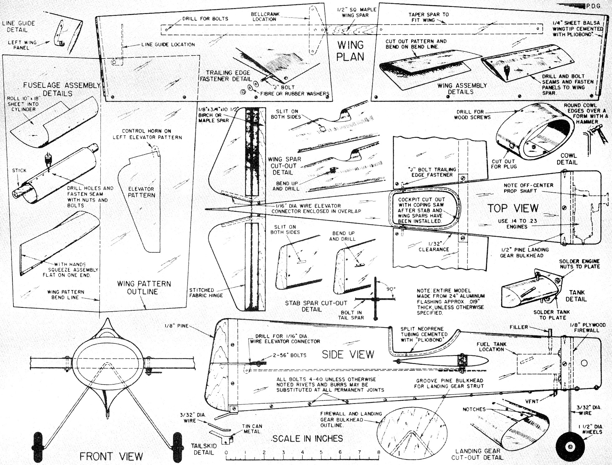
Sheet Metal Suzie Cut-Away View
Stop in at your local building material outlet and ask for a couple feet of 24" aluminum flashing.
This shouldn't cost over 75¢. This stuff should mike (micrometer) about .019; don't get the heavy-duty
.024 grade.
Note that this material has a "grain," that is the long way and you'll get a better and easier job
by observing the lay of the metal. Cut out a piece 18" x 10" and roll this into a cylinder, then get
your perimeter dimension by setting the bulkhead in place in one end, mark and then remove the bulkhead,
line up the cylinder, prick and drill and bolt the edges together with 1/4" round head 4-40 bolts and
nuts. (Riveting is okay if you have the equipment.)
Now observe the inside edge of the lap-joint; this must come at the bottom right (outside) fuselage.
With this in mind gently squeeze the tube into shape to receive the tail piece, the wood rudder, and
bolt this in place. Run a #3 drill through the sides, taking care to be perpendicular to the rudder
piece and then carefully slit the fuselage as shown and bend the resulting tab upward on each side.
Drill and bolt the hardwood stabilizer to these tabs - a modicum of bending is permissible if necessary
for good alignment.
Set the fuselage aside and make up the engine - mount - bulkhead - tank - landing gear assembly.
This is a separate and independent unit and note that the engine shaft will be off-center to the left;
regardless of what engine you use, the shaft position will be dictated by having just the glow plug
tip project beyond the fuselage side. This permits use of the popular "flat-opposed" type of engine
cowl. Next take the nose assembly and stick it into the open fuselage end - line your assemblies up
simply by twisting one way or the other, and when you are satisfied with the alignment notch out the
fuselage end - line your assemblies up simply by twisting one way or the other, and when you are satisfied
with the alignment notch out the fuselage metal around the landing gear legs - this will maintain the
arrangement. You may wish to drill for the wood screws now and put them in place temporarily.
With a straightedge draw pencil lines down each side from the stabilizer center to the centering
marks on the bulkhead. Balance the assembly between fingertips and mark at this point. (This will vary
somewhat between the ultra-light Cub .14 and something heavier, like an O&R .23). Do not make any
allowances for missing elevators or prop, but cut for the spar at this point in similar fashion as for
the stabilizer-spar, except that the tabs here are on the bottom. Poke the wing spar into place, drill
and bolt temporarily.
Only at this time do we cut out the cockpit. Use a coping saw and leave the edges rough, smear with
Pliobond cement, slit a 12 1/2" length of heavy-wall black neoprene tubing and push it in place as moulding
around the cockpit rim.
Sheet Metal Suzie Plans
Full-size plans for Sheet Metal Susie are found on Group Plan #356 by Hobby Helpers, 770 Hunts Point
Ave. New York 59, N. Y. (35c)
To Be Continued
Posted March 28, 2016
|