|
While doing research on
rocket-powered gliders and
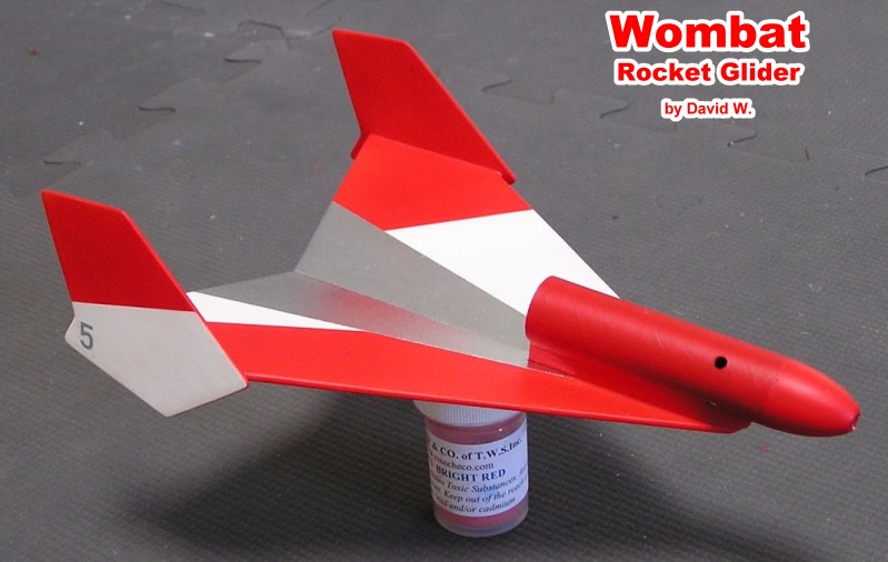
boost-glide rockets, I ran across the Wombat rocket-boost glider
design and tried to find either a source for buying a kit or for
buying the plans. Neither seem to be available - at least not for
me. When I posted a photo of David Wagner's Wombat, I requested
knowledge of a source for plans and someone send me an old scanned
set. I cleaned them up and posted them here. If you are the
copyright owner and do not wish to have them posted, please let
me know and I will remove them posthaste.
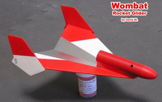
Your Wombat glider has been designed with simplicity, durability
and strength in mind. If you follow the Instructions closely, your
glider will afford many beautiful flights. Read the following Instructions
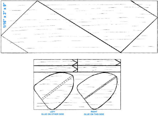
completely before you start construction. For best results, trace
the fin and wing patterns accurately since the glider flies best
with these particular patterns. You will need the following:
model cement, a hobby knife, fine sandpaper, and two catalogs or
large books. Step 1. Check your kit to identify all parts. You should
have: 1. 1 3" by 9" sheet 3/32"
balsa 2. 2 7/8" by 5" sheet 1/16"
balsa 3. 2 3/4" body tube 4.
1 Balsa nose cone 5. 1
1" x 5" metal sheet (rib) 6. 1
Launching lug 7. 1 Fin pattern
sheet Step 2. Cut the fin patterns from the pattern sheet.
Lay them on the balsa as shown on the sheet and trace them onto
the balsa sheet, being aware of the direction of the grain. Cut
out the wings, stabilizers, pylon sections and glue spreader.
Step 3. Sand all parts so they are the same size as shown on the
patterns. You may wish to round the corners on the pylon pans for
appearance and performance; it is advisable to sand them after gluing
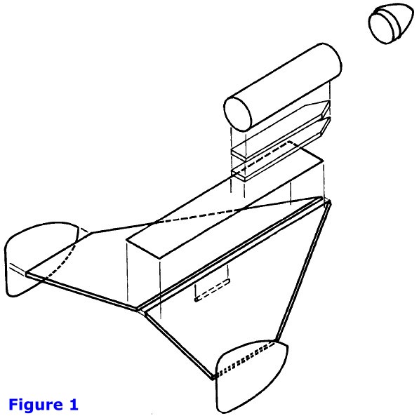
them together as you will be assured a better fit.Step 4.
Glue the pylon parts together and set aside to dry. Next, glue the
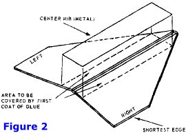
wings together as shown in Figure 2. Be sure that the cement rib
(metal sheet) is well centered on the joint between wings. For best
results, apply a coat of glue to one side of the rib and to the
area on the wings where you intend to glue the rib. Let this coat
dry at about 10 minutes before applying a second coat to the wood
and finally gluing all 3 parts together. Put the wing assembly between
two sheets of scrap paper and under several large catalos or books
so that it will dry flat and even. Step 5. While the wing
is drying, you may sand the corners of the pylon until they are
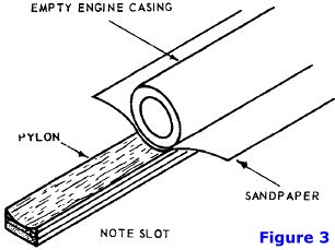
slightly rounded. Using an empty engine casing wrapped with sand-paper,
sand a shallow slot into one side of the pylon so that the curve
of the slot fits around the body rube. (See figure 3). This slot
need not be deep since its only purpose is to increase the gluing
area between tube and pylon. Step 6. Apply a coat of glue
to the slot and to a portion of the body tube of the same size as
the pylon. Let this coat dry about 5 minutes. Apply a second coat
to the pylon slot and glue the pylon to the body tube so that the
blunt end of the pylon is flush with one end of tube. Set aside
to dry. Step 7. When your wing assembly is dry enough to
handle (about 30 minute, after gluing) remove the catalog, or book
and place it on a flat surface. Next, apply a coat of glue to the
shortest edges and let it dry. Meanwhile, apply a similar coat of
glue to the center of the vertical stabilizers along the lines shown
in the fin patterns. Be sure you apply the glue on the correct side
of each stabilizer; you may check by comparing each stabilizer with
the one on the pattern sheet with reference to grain and indicating
notes. After these coats of glue are dry, apply a second
coat to the shortest edges of the wing and glue a single stabilizer
to one edge of me wing. Be sure the pointed end of the stabilizer
fits flush with the front end of the shortest edge of the wing.
Place the wing between the books so that it is held with the attached
stabilizer above the books; that is, place the wing perpendicular
to the table on which you're working. When that stabilizer
is dry, attach the other one in the same way. Allow this assembly
to dry at least 10 minutes before proceeding. Step 8. Apply
a coat of glue to the flat side of the pylon which should now be
glued to me body tube. Let the coat dry for several minutes before
applying a second coat. Glue the pylon tube assembly to the wing
so that the pointed end of the pylon and wing are glued at the same
point. Align the body tube so that it points down the center of
the whole glider. This alignment is very important - if the body
tube is glued off to one side, or is pointing to one side, the rocket
will loop and crash upon takeoff. Step 9. While the tube-wing
assembly is drying, glue the launching lug to the wing about 2½"
to 3" from the front of the wing. Set aside the glider to dry with
the body tube (pod) up. Step 10. When your completed glider
is dry, round the edges of the wing and stabilizers to decrease
drag and turbulence.
Step
11. After the glider is completely dry, take it outdoors or to a
large, open space for flight testing. Hand toss by grasping the
launching lug and throwing it lightly into the wind. If the glider
drifts to one side, sand the bottom of the wing on that side. For
example, if your glider drifts to the right, sand the area behind
the launch lug on the light side. Keep in mind that the right side
when the pod is up is the left side when you flip the glider over
for sanding. If your glider refuses to glide at all, sand the area
behind the launch lug so that the trailing edge of the wing tapers.
If your glider stalls (nose turns up and rocket falls), add a small
amount of weight to the nose cone. Adding or subtracting weight
in a light glider like the Wombat is critical so use pieces of cardboard
glued together to add just the right amount. Step 12 When
your glider is properly trimmed, you may wish to paint it. To obtain
a smooth finish, apply one or two coats of sanding sealer, let dry
and sand with very fine sandpaper between coats. Spray with red-orange
or fluorescent red-orange paint for best visibility. Step
13. After you have completed painting, test-glide your Wombat once
more and add or subtract weight as is necessary. When you are satisfied
with the glide, glue your nose cone in place. You may wish
to alter your Wombat for use in accordance with NAR rules.
To do so, simply cut off the rear 1" of the body tube. Whenever
you fly your glider, tape a 1" wide streamer to the rear of the
engine and wrap it around several times. Tuck the loose end of the
streamer between the pylon and the engine so that it won't flutter
or come loose on takeoff. Be sure to test glide your Wombat after
removing the 1" of body tube since you may have to adjust for the
loss of weight of the body cube. The Wombat should be launched from
a 36" launching rod, Electrical ignition must be used at all times
and it is safest to fly the Wombat when winds are under 20 miles
per hour. If you are using a small area, use only ½A's
and A's. A and B engines will give more spectacular flights but
you stand a greater chance of losing your glider. Good luck and
good flying!
Wombat Printwood Patterns
Posted December 7, 2013
|