|
In 1963, when this article
was published in American Modeler magazine, it had only been 18 years since the
end of World War II, where the Grumman F4F-3 Wildcat earned its place in the history
books as the only fighter in the U.S. armed forces' inventory capable of taking
on Japan's Zero fighter.
None other than the inestimable
Walter A. Musciano designed this 38" wingspan control line model fashioned after
ace fighter pilot Joe Foss' Wildcat. It used a .29 size engine, but could easily
be converted to electric power. Construction is very typical of the day: rugged
and heavy, but durable. Some lightening effort is advised if using electric power.
Control Liner Grumman Wildcat
 By Walter A. Musciano By Walter A. MuscianoFlying scale fans
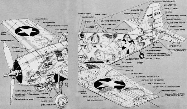
are certain to hail these detailed plans for one of the Navy's best known fighters,
the F4F-3 Grumman. Scaled one inch to the foot Walt's model has a wingspan of thirty-eight
inches, takes a glow plug engine from .29 (in very good health!) to .60. Hobby Helpers
has full size drawings on Plan #663 for
Control Liner Grumman Wildcat
When the Japanese task force struck at Pearl Harbor December 7, 1941, the United
States was woefully unprepared to battle the vaunted Mitsubishi Zero fighter. Only
one airplane in Uncle Sam's arsenal proved itself against the Japanese Naval menace
and this was the Wildcat, Grumman's first venture with monoplane all metal fighters.
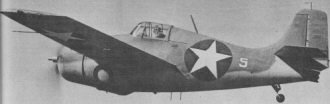
The most used version of this distinctive mid-wing design, the F4F-3, was the U.S.
Navy's first line standard fighter and bore the brunt of the fighting in the South
Pacific throughout 1942-1943 until it was replaced by the newer Hellcat and Corsair.
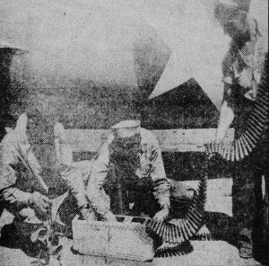
One of the most famous "Wildcat" pilots was Joe Foss whose exploits
have been detailed in the recent April/May 1963 issue of "Air Progress" magazine.
Plans show markings taken from Foss' Grumman. The ace is seen checking ammunition
containers.
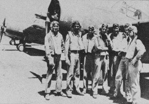
Joe Foss with members of his flight.
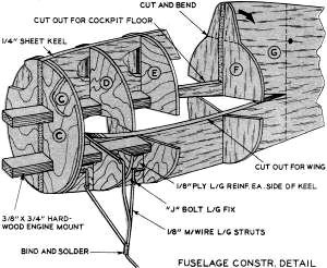
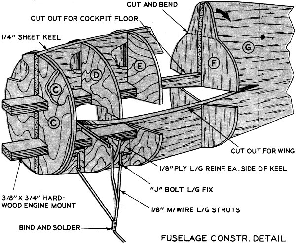
Fuselage construction detail.
The Grumman F4F-3 Wildcat was powered by a Pratt & Whitney Twin Wasp 1,200-hp
engine which enabled the 6,100-lb craft to reach a top speed of 325-mph. Ceiling
was 31,000 feet; cruising range at 297-mph was 1,120 miles. Six .50 caliber machine
guns were fitted in the rigid wings of most production Wildcats. Some later models
featured manually folding wings to facilitate storage aboard aircraft carriers.
The F4F design saw extensive service with both the U.S. Navy and Marine Corps. Many
more were delivered to England and these were called Martlets. The Wildcat was one
of the first U.S. planes to employ self-sealing fuel tanks and protective armor
for the pilot.
Its relatively light weight and large wing area made the Wildcat extremely maneuverable
and, therefore, more of a match for the Zero than the P-39 or P-40. In addition,
the F4F was able to withstand considerable punishment from the enemy guns. Very
few Wildcats went down in flames. It was with planes such as these that men like
O'Hare, Hansen, and Foss were able to exact a terrific toll of Japanese aircraft
over the Solomon Islands in the South Pacific as well as Wake Island in the north
during our follow-up rounds in the Pacific.
Presented here is a control line model patterned after one of the Grumman fighters
flown by Ace Joe Foss over Guadalcanal. It is scaled one inch to the foot which
provides a general 38" wing span. Most any engine from a healthy .29 to a quiet
.60 cubic inch displacement can be installed in the roomy nose. We recommend a .35
or .40 as ideal for all-round sport flying.
Construction begins with the wing. Cut spars and joiners, assemble these with
proper dihedral. Cut ribs while assembly is drying. Cement ribs to spar fitting
notches together, then cement bellcrank mount in place. Attach lead-out lines to
bellcrank, slip these through rib holes. Bend wire control rod end, slip it into
bellcrank. Bolt bell crank to mount. Cut leading edge and cement to ribs.
Butt join 1/8" balsa sheet covering to equal chord width of wing, then cut to
wing outline. Cement lower covering to spar, ribs and leading edge. Hold with pins
until dry. Bevel trailing edge of lower covering to follow upper camber contour,
then cement upper covering in place, using plenty of cement especially along beveled
lower covering. Rough-cut wing tips, drill for lead-out lines, cement to tip ribs.
Set wing aside to dry.
Cut fuselage keel, formers, and engine mounts. Cut the elevator and stabilizer,
sand to streamline section. Cement elevator halves to hardwood joiner, install control
horn. Hinge stab to elevator, cement stab to keel top which also forms lower portion
of fin.
Sandpaper wing structure thoroughly, then slip it through fuselage keel opening.
Apply lots of cement when wing is aligned with keel and stabilizer. For a "commercial"
fuel tank it will be necessary to cut away a bit of the wing as shown. (This does
not affect overall strength because the spar is the main supporting member.) Fit
tank in snugly by cutting through keel. Add plastic tube filling, vent, and feed
lines; tape their ends to keep out dirt. Slip hardwood engine mounts through bulkhead
holes and cement well. Add mount locks with lots of cement. Drill 1/8" hole through
hardwood, then cement dowel into hole. Re-cement engine mount joints. Support tank
with straps and/or with balsa wedges.
Cement fuselage formers in their proper locations - first slip control rod through
former holes. Connect control rod to elevator horn, then check out control system.
Bend landing gear struts. Note only three attach to plywood foundations; remainder
are fitted just for the scale effect. Install three main struts and hold with "J"
bolts. Bind struts together with soft fine wire ... not aluminum wire. When struts
are in position, solder joint. Secondary struts covered with thin plastic fuel line
for scale appearance are now added.
Plank entire fuselage with balsa strips ... cement thoroughly to each other and
to formers. Upon completion force Plastic Balsa into any small spaces left between
planking. When thoroughly dry, sand fuselage with fine, then very fine, sandpaper.
Note fuselage fin fairs into turtledeck by a large fillet. Cut this from sheet
balsa and cement it on each side of fin between fuselage and stabilizer. Add upper
portion of fin atop stabilizer. Sand this installation then continue the fillet
with Plastic Balsa. Cut, carve and sand rudder, cement to fin offset as shown. Apply
several coats of cement along wing and tail joints to form a small fillet and strengthen
the joint. Large fillets here are not required.
Cowl is four balsa blocks assembled along vertical and horizontal center lines.
This facilitates separation later and keeps cost low. When cement is dry, carve
cowl to its external shape and sand smooth. Then carve the interior with an X-Acto
gouge. You can separate the cowl along one of the centerlines or work on it in one
piece. Cut cylinder opening to fit motor.
Apply three heavy coats of Balsa Filler Coat to entire model, sand thoroughly
when dry. Continue applying Balsa Filler Coat, with a light sanding after each,
until finish is glass smooth. Thin final coats with ten percent thinner. We do final
sandings with Flex-I-Grit abrasive-coated Mylar. We are now ready to paint.
Entire underside of model gets very light-blue dope, slightly tinted with green
as per mixing instructions. Upper surfaces then are painted medium greenish-blue
... the color separating line must be wavy and hazy. A fine spray gun or artist's
air brush is ideal for achieving this effect. If these are not available, light
sanding with Flex-I-Grit and rubbing compound creates a hazy separation line.
Add cockpit canopy, interior, antenna mast, Wondur-Cals, wheel covers, wheels,
and other details. Install engine, attach cowl. Use three-bladed propeller for optimum
realism.
Balance completed craft as per plans via lead weight firmly fastened in extreme
nose or tail. Use flight lines not less than .012" diameter. Their length depends
upon your flying experience; we prefer to test fly on relatively short 40' lines,
then gradually increase to 70'. A paved take-off and landing area is mandatory.
An American Junior U-Reely control handle lets you take off from a restricted paved
area on short lines, then unreel for some long line flying. Craft is reeled in for
landing.
ACKNOWLEDGEMENT. The cooperation of A.E. Ferko and N.H. Hauprich, and their extensive
knowledge of military aviation history, was indispensible to this article and is
sincerely appreciated by the author.
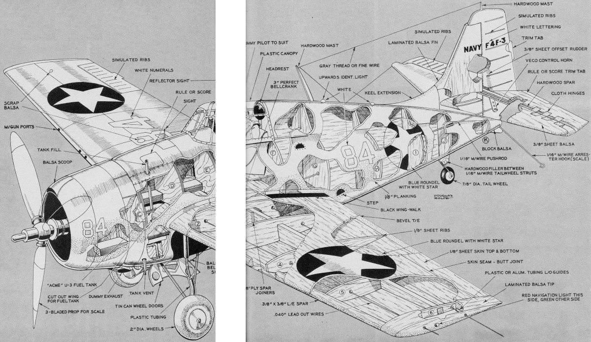
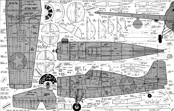
Airframe Construction Drawing
(missing area in center due to magazine printing omission)
<click for larger version>
Grumman Wildcat Plans
<click for larger version>
Notice:
The AMA Plans Service offers a
full-size version of many of the plans show here at a very reasonable cost. They
will scale the plans any size for you. It is always best to buy printed plans because
my scanner versions often have distortions that can cause parts to fit poorly. Purchasing
plans also help to support the operation of the
Academy of Model Aeronautics - the #1
advocate for model aviation throughout the world. If the AMA no longer has this
plan on file, I will be glad to send you my higher resolution version.
Try my Scale Calculator for
Model Airplane Plans.
Posted January 19, 2024
(updated from original
post on 10/6/2012)
|