|
Here
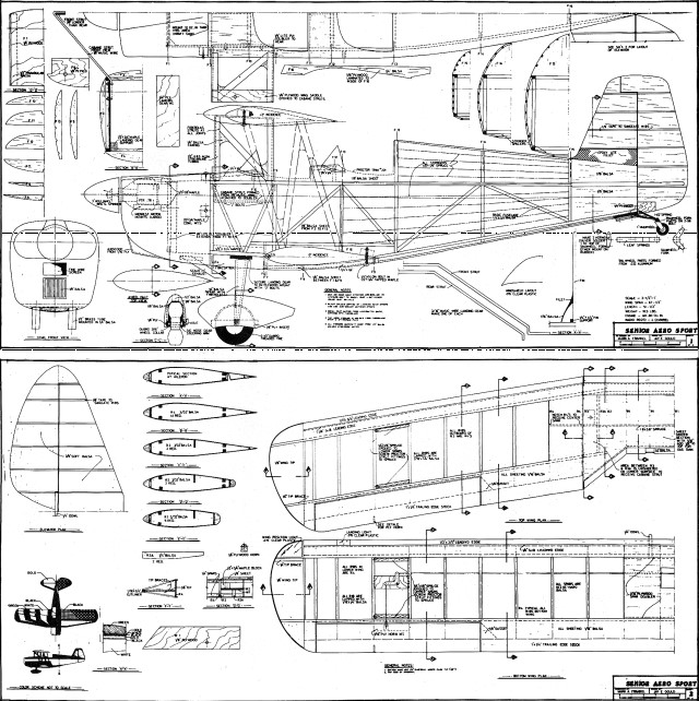
is the article and plans for the Senior Aero Sport that I electronically
scanned from my purchased copy of the March 1975 American Aircraft
Modeler magazine. You might be able to scale up the image below
if you cannot find suitable plans for sale. Plans for this fine
model were drawn by Mr. Mark Frankel. All copyrights (if any) are
hereby acknowledged. Bipes are beauteous ... they're
dramatically angular, yet subtly curved; antique in mood, but modern
in spirit. They possess an eloquence that is awkwardly graceful.
/by Mark Frankel With 67%" of span, the Senior Aero Sport
aims for realistic flight performance-it's like a biwinged Senior
Falcon in the air.
 Have
you ever noticed how realistically a really large scale model behaves
in the air? As the model's size increases, its power-to- weight
ratio, wing loading, and other aerodynamic characteristics (such
as Reynold's number) apparently begin to approximate the full-sized
aircraft's. So, in addition to the static appearance of a real plane,
the large scale model presents the added thrill of handling like
the real thing. Have
you ever noticed how realistically a really large scale model behaves
in the air? As the model's size increases, its power-to- weight
ratio, wing loading, and other aerodynamic characteristics (such
as Reynold's number) apparently begin to approximate the full-sized
aircraft's. So, in addition to the static appearance of a real plane,
the large scale model presents the added thrill of handling like
the real thing.
 The
Sport Biplane event, as proposed by Jerry Nelson, seems aimed at
capturing some of that realism in Pattern-type competition. The
NSPA rules are clearly intended to simulate the barnstorming stunts
and aerobatics of full-sized aircraft, as opposed to the AMA and
FAI Pattern events, which feature overpowered missiles performing
feats that no man or machine could survive. The
Sport Biplane event, as proposed by Jerry Nelson, seems aimed at
capturing some of that realism in Pattern-type competition. The
NSPA rules are clearly intended to simulate the barnstorming stunts
and aerobatics of full-sized aircraft, as opposed to the AMA and
FAI Pattern events, which feature overpowered missiles performing
feats that no man or machine could survive. The Senior Aero
Sport is an example of a large model that satisfies the philosophy
of the Sport Biplane event. Furthermore, its exact scale outline
allows it to compete in the AMA as well as Stand-off Scale events.
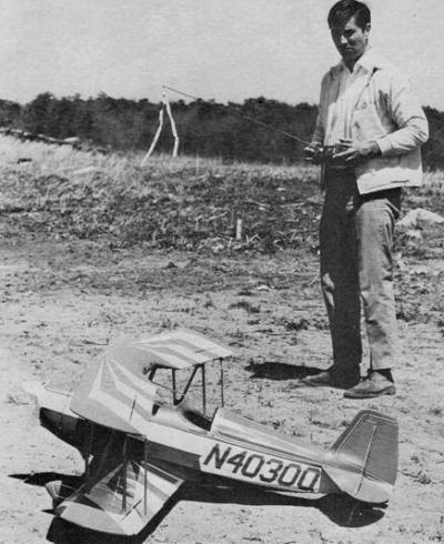
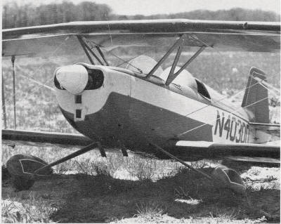
The author taxis the Aero Sport out for another aerobatic
practice session. The shot gives some perspective of the dimensions
of this 10% lb. dream ship.
I considered building the Senior Aero Sport for several years; however,
various obstacles (such as military service) kept me from undertaking
the project. Fortunately, I discovered that the designer of the
full-sized aircraft, Nicholas D'Apuzzo, lives in my general area.
Mr. D'Apuzzo supplied me with three-view drawings of the aircraft
and several photographs of various versions constructed by homebuilders
across the country. He also provided me with a list of completed
Senior Aero Sport projects, including the names and addresses of
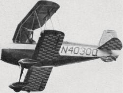
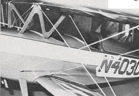
the builders. It turned out that two outstanding examples,
Jim rankenfield's N 112JF, and Tom Luckey's N4030Q, were hangared
nearby. An inspection of these aircraft would humble even the most
gifted model builder. Tom Luckey's biplane, the aircraft that I
chose to model, won the "Grand Champion Homebuilt" award at the
1968 EAA International Convention. Jim Frankenfield's airplane,
featuring a beautiful paint scheme, also has won many awards. It
is a very photogenic airplane and, consequently, has been the subject
of many homebuilt aircraft articles. Tom Luckey's N4030Q
is now owned by Alvin Levenson, who hangars it at Zahn's Airport
on Long Island, N.Y. When I visited Mr. Levenson, I found that he
had enhanced its beauty by re-upholstering the interior, adding
Navy squadron insignias to the fin, and chrome-plating the spinner.
Jim Frankenfield's N 112JF is currently based at Executive Airport
in Ft. Lauderdale, Fla.
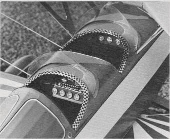
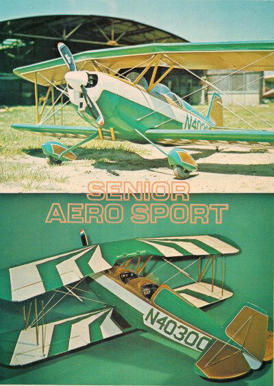
The paint scheme is dashing, with straight lines playing across
and around curved form.
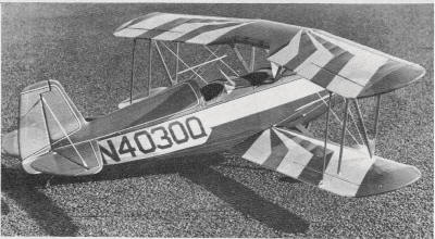
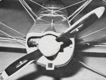
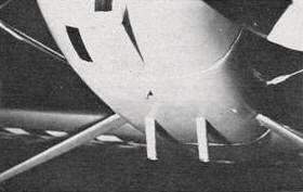
A side-mounted Fox 78 gives plenty of power for the NSPA aerobatic
sequence. The engine is well-disguised in the cavernous cowl.
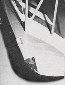
Checkerboard underpainting adds to design's racy appearance.
Detailed cockpits aren't very difficult on a model this size.
They add that final touch to any project.
Of course, there are many other examples of the Senior Aero
Sport across the U.S.-I even heard of a Navy lieutenant who was
building one aboard the USS Roosevelt! I'm sure that a letter to
any owner would bring mounds of photographs and other scale data
for your modeling project. And, a letter to Nicholas D'Apuzzo, 1029
Blue Rock Lane, Blue Bell, Pa., (with a check for $3.00) will get
you a set of three-views, with photographs and a list of all completed
Senior Aero Sports. In addition to these sources, the following
periodicals contain certain information on the Senior Aero Sport:
Sport Flying, February and August, 1970; Flight Digest, fall
1969; Sport Aviation, March, 1961 (this article covers the PJ-260,
single-place version, forerunner of the Senior Aero Sport), and
November, 1968 (Cover Photo of N112JF). If you have any trouble
obtaining scale documentation, please send me a letter in care of
AAM, and I might be able to help. CONSTRUCTION
Construction of the model can begin with any of
the major components: wings, fuselage , or tail surfaces. I'll describe
wing construction first, as it represents the major time investment.
Wings: Begin by cutting forty-four R4, two R3A, two R3, two
R2 and five R1 ribs. Pin and glue the trailing edge stock and the
lower rear spar on the lower TE sheeting. The ribs are then glued
into position, followed by the upper rear spar and sheeting, the
two forward spars, and the 1/8" sub-leading edge [this 1/8" provides
a base for the 1/16" LE sheeting)_ When completely dry,
remove the wing panel from the building board and add the LE sheeting.
The LE of 1/2 x 3/4" soft balsa is then
glued into position and carved to shape. At this point, the ailerons
can be cut from the wing panel. Use an X-acto razor saw with the
stiffener removed; the blade will remain stiff enough to make a
fine cut through the trailing edge. After installing the aileron
control horns, the wing and ailerons are faced with 1/8" balsa.
The 1/8" facing on the wing panel will be resting against the rear
spar. The aileron hinges pass through this facing into the upper
rear spar. The wing tips can be added now, followed by 1/16
x 1/4" balsa cap strips on all ribs not covered by center section
sheeting. After careful sanding, the lower wing panels are ready
for joining. The lower wing has a 1/2°
dihedral angle, or 1/4" elevation under each tip. Epoxy a 1/16"
dihedral brace to both the rear and forward spars. The upper
wing panels are joined through a center section constructed of the
remaining ribs. The 1/8" plywood W1s are epoxied between R2 and
R3. It is important that W1 is glued on the chord line of R2 and
R3, since any deviation will affect the incidence of the upper wing.
Epoxy the outer panels to the center section so that R3 butts against
the first R4 and all four of the panel's spars butt against R2,
and the center section's 5/8 x 1/8" spruce spar fits into the first
two R4s. Now, epoxy scrap blocks of balsa between the spars
and W 1 to bring the spars in contact with W1. Glue maple blocks
to the upper surface of W1 to receive the wing mounting bolts. Use
1/16" sheet balsa to cover the center sections of both wings as
shown on the plans and wrap both wings with fiberglass strips at
the wing panel joints.
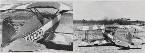
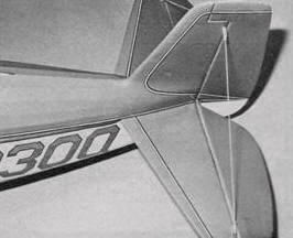
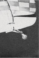
Being a homebuilt project, the Aero Sport-seen from two angles
here-has plenty of scale documentation readily available. The
full-size plane won the EAA's Grand Champion Homebuilt Award.
In some Senior Aero Sports the center section of the upper
wing carries fuel, so it is a bit thicker than the outboard panels.
This can be simulated by adding a layer of 1/8" sheet balsa to the
upper surface of the center section. The bottom of the center section
is left open between R 3 and R 3A to receive the cabane struts.
Note that some of the lower rear spar will have to be trimmed to
allow proper seating of the wing on the cabane struts.
Details, Details, Details
Before covering the wings be sure to epoxy 1/8 x 1/4" spruce
strips to the spars as shown on the plans. These strips serve as
mounts for the Proctor strut brackets (Proctor scale accessory No.
315). Fuselage and Cowl: The basic fuselage
is simply a box structure formed from two built-up sides of % x
%" balsa. A 1/8" plywood doubler is epoxied to the inside of each
fuselage side. This doubler supports the firewall (F 1), the 1/8"
music wire cabane struts, and the landing gear mount. The
basic box structure is formed by gluing F 1 and all cross members
into position between the two sides. Now all formers and stringers
are added; the music wire cabane strut is secured with "J" bolts;
and the 1/4" plywood landing gear mount is epoxied into position.
The next task is to install the fuel tank behind F 1, followed by
the main landing gear which is fabricated from two 3/16" music wire
struts. The gap between the struts is filled with balsa
and fiberglassed to simulate Cessna-type landing gear. I avoided
commercially available sheet metal landing gear because none was
large enough, nor were the struts narrow enough to give a scale
appearance. The 3/16" struts are bolted to the 1/4" plywood mount
with "J" bolts. Note that the fuselage doublers are lined
with 1/2 x 3/4" maple rails on the lower edge. These provide a strong
gluing surface for the 1/4" plywood landing gear mount. Once the
internal work is completed, the forward portion of the fuselage
is sheeted with 1 /8" balsa and a 1" balsa block is added between
F4 and F6. After sanding, the cockpit openings are cut from the
upper sheeting. I formed my cowl over a foam mold. I like
to work with foam, since it carves and sands easily and is relatively
inexpensive. The major disadvantage is that the mold must be destroyed
to free the finished component. To build the Senior Aero Sport's
cowl, simply laminate foam blocks forward of F2, F3, and F4 to match
the approximate shape of the cowl. Three-M's Sprayment is excellent
for laminating foam. Be sure the foam adheres to the fuselage structure
only at F2, F3 and F4. This will allow easy removal by simply cutting
the mold free on that line. If the mold adheres to the doublers
or firewall, it may be impossible to remove in one piece. When shaping
the foam, try to sand it approximately 1/16" undersize in all dimensions
to compensate for the thickness of the fiberglass cloth.
After removing the mold from the fuselage, glue a hardwood strip
to the inside. This "stem" can be mounted to a vise to hold the
mold while you apply the fiberglass cloth. I applied five layers
of medium-weight cloth to the mold, each held in place with 3M Sprayment.
The cloth is then liberally saturated with Hobbypoxy Formula II
and allowed to cure. The mold is removed by dissolving it with lacquer
thinner. The exterior of the cowl is then smoothed by mounting it
on the fuselage and adding a layer of Epoxolite. When the Epoxolite
is sanded smooth, the necessary openings for ventilation can be
cut. Tail Surfaces: The tail surfaces are
formed from light 3/8" sheet balsa. The elevators are joined by
a 1/4" dowel, and 1 /8" masking tape is used under the covering
to simulate ribs on the tail surfaces. The wheel pants are carved
from laminated balsa. The pant is retained on the axle by a Sig
nose wheel steering arm (drilled to receive the 3/16" axle), which
is bolted to the plywood insert on either wheel pant. The entire
wheel pant is covered with fiberglass cloth and coated with finishing
resin or epoxy. The tail wheel strut is fabricated from
.032 K&S aluminum. The "N" struts are built from %" K&S
streamlined tubing. Each strut is cut to length after the wings
are bolted into position. The forward and rear struts fit into Proctor
strut mounting brackets. The diagonal member is epoxied between
the two upright members. When dry, the strut assembly is removed
from the brackets; the joints are fiberglassed and blended smooth
with Epoxolite. Finishing and Rigging:
With the exception of the cowl and wheel pants, my entire airframe
was covered with Silkspun Coverite. Be sure to use an iron that
produces enough heat to effectively seal the Coverite. Once the
model is covered, the rigging can be fitted. Use white elastic cord
for the flying wires. The cord is cut to approximately three-quarters
of the distance between the points of attachment. Goldberg "Mini-Snap"
nylon clevises are knotted on each end of the elastic cord. The
nylon clevises not only simulate the clevises used on full-size
biplanes, but allow quick assembly or breakdown of the rigging.
I
used Du-Bro metal landing gear straps for anchoring the flying wires
to the airplane. The straps are screwed into hardwood in such places
as the "N" strut attachments or they can be inserted into the wood
and epoxied in such places as the fuselage and tail surfaces.
I painted my model with acrylic lacquer plasticized by Southern
R/C Product's Flex-All. Two coats of primer were applied and sanded.
Then the entire airplane was sanded with three coats of white. After
the white had completely dried, I masked for the first trim color,
gold. The checkerboard pattern on the lower flying surfaces
was masked by identically cut squares of vinyl contact paper. Avoid
applying extremely wet coats of lacquer over the contact paper,
as it tends to lift when covered with excess paint. The final color,
green, is followed by the addition of pinstripes - black pinstripes
on all lines where gold meets white, and gold pinstripes where green
meets white. Goldberg's Multi-Stripe tape is recommended. I then
added two coats of clear lacquer to seal the finish. You may
want to try clear Super-Poxy, since it probably will provide a harder
finish. Windshields of .015 clear plastic are attached to
the fuselage with Ambroid Cement. Cockpit detail, such as instrument
panels and seats, can be added at this point. Another advantage
of a large scale model is that the radio gear can be easily hidden
to permit an unencumbered cockpit. I mounted the servos horizontally
under the rear seat. The batteries and receiver were placed just
above the landing gear mount, forward of the front cockpit.
FLYING A reliable radio and engine,
coupled with a warp-free structure and a properly located CG should
ensure a well-flying model. Unfortunately, my first flight was not
trouble-free, since I built my model with scale wing incidence of
20 in both wings. This is far too much incidence for the model,
and the Senior Aero Sport staggered into the air at a dangerously
low airspeed. Even with considerable down elevator, it flew in a
nose-high attitude. After a full stall landing (literally), I realigned
the wing incidence and the Senior Aero Sport has behaved like an
airplane ever since. The plans reflect the current setup of 20 in
the upper wing and 00 in the lower. I am using a Fox .78
with a 14 x 6 Top Flite prop. This power combination is ideal for
effortless takeoffs and large,
Notice:
The AMA Plans Service offers a
full-size version of many of the plans show here at a very reasonable cost. They
will scale the plans any size for you. It is always best to buy printed plans because
my scanner versions often have distortions that can cause parts to fit poorly. Purchasing
plans also help to support the operation of the
Academy of Model Aeronautics - the #1
advocate for model aviation throughout the world. If the AMA no longer has this
plan on file, I will be glad to send you my higher resolution version.
Try my Scale Calculator for
Model Airplane Plans.
|