|
Website visitor Gordon W. requested a copy of this
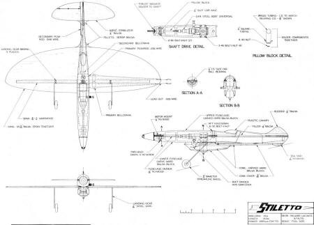
article for the Stiletto that appeared in the December 1970 American Aircraft Modeler. This unique 1/2A
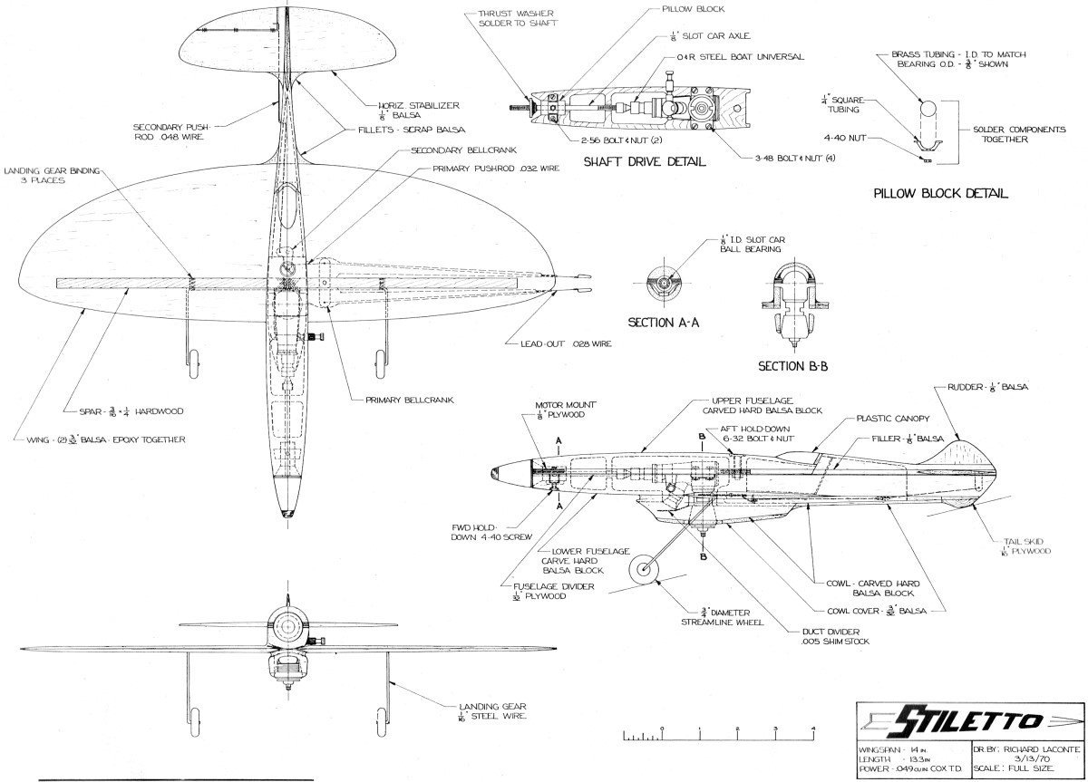
racer uses a 2-1/2" slot car axel as a prop extension to create the long nose moment with a center-mounted
engine. A boat universal joint provides the interface. Stiletto
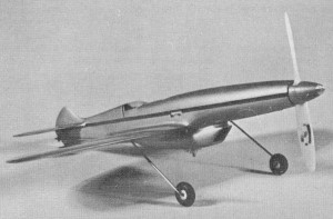
Unique appearance and superior streamlining are achieved on this 112 A Proto racer with simple shaft
extension. Idea would work on any size speed model. by Richard LaConte THE PROTO SPEED
MODEL, by defini-tion, is supposed to resemble a full size airplane, but in order to achieve good aerodynamic
design, these models now are looking more like-to quote the Con-test Director of the '69 Nats - "Hell
Razors on Wheels." The Stiletto is in-tended as a step toward the original in-tent of the Proto rules
and as an effi-cient aerodynamic design. Several areas of design improvement were explored.
When it is reworked, the 049 engine, because of its size, does not respond with large increases in power,
and some engines seem to be at their peak in stock condition. Since few gains are to be made in engine
modifications, the next logical place for improvement is in aerodynamic design, beginning with the propeller.
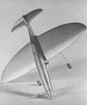 This futuristic-looking plane
resembles ideas seen in Air Trails of the '40's.
 Long nose makes prop more efficient.
Engine weight at CG results in very maneuverable model, yet design is quite stable.
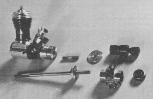 Long prop shaft and associated
parts are standard off-the-shelf items, such as a slot-car axle, bearing, and boat universal.
Little information is available on model propeller performance, except that such propellers are very
inefficient when compared with full size counterparts, and that the airflow is extremely tur-bulent
and forms a spiral around the fuselage. To obtain maximum use from the prop wash, the maximum cross-sec-tional
area of the fuselage is best placed as far aft of the propeller as possible. In present designs, the
forward location of the engine puts the maximum cross-sectional area just aft of the propeller and any
attempt to reduce the area is limited by engine size. Also, the abrupt vertical rise of the cowling
does an ef-fective job of disrupting the prop wash before it can stabilize its flow. With the
amid ship location of the Stiletto's engine, this design succeeds in obtaining the desirable aft location
of the maximum cross-sectional area and at the same time creates a sleek and realistic looking model.
Other benefits obtained from this engine location are being able to use larger intake ducts for the
carburetor and cooling and-of in-terest to stunt enthusiasts-a reduced rotational moment of inertia
due to the larger mass of the engine being placed near the aerodynamic center of the wing. This results
in an airplane that is high-ly responsive to the controls. Now comes the question-does the amidships
location of the engine increase the performance? A 1967 prototype used a Cox Space Hopper engine which
had given consistent : Protospeed runs of 64 to 68 mph under W.A.M. rules in Cali-fornia. A 12-in. minimum
wingspan and no minimum area were specified. The prototype, built to AMA specifications, weighed a heavy
8'4 oz. Several drive systems were tried, and the Stiletto is the design which finally evolved.
About 20 flights were made with the prototype, using a 4"h-7 Rev-up prop to be consistent with the
old Protospeed engine runs. The unofficial speed range of the test flights was 71 to 78 mph, indicating
a substantial increase in per-formance. High winds and a control failure brought the prototype to a
crash-ing end. Then the Stiletto was built but, due to unfavorable weather conditions and a new engine,
it was not flown for a speed run. Initial flights did show ex-cellent handling characteristics and a
potential for high speeds. Both the Stilet-to and its prototype are quite stable, but yet extremely
responsive to con-trols. Construction Construction is broken down into two main parts:
(1) the drive system and (2) the airframe. The shaft drive system is the heart of the Stiletto
and care must be taken in its construction. All components are easily obtained at any hobby shop that
stocks model airplane, boat, and slot-car parts. The engine is a Cox 049 Tee Dee in stock condition.
Its needle valve is rotated to a forward position, and the edge of the valve body radiused to clear
the crankcase. The universal joint is an a & R steel boat universal with 5-40 threads at
either end. Steel is preferred, but brass may be used if the ball end is inspected for wear before and
after each flight. Thrust loading on the brass universal tends to cause abnormal wear on. the ball and
it may break off in flight. The drive shaft is a 1/8 x 4" steel slot-car axle with 5-40 threads.
The thrust washer is made up of a nut and washer grooved on the prop side and soldered to the shaft.
The shaft is supported at the end by a 1/8" ID slot-car ball bearing in a pillow block made of brass
tubing (shown in detail on the drawing). The OD of the bearing is not critical and may vary according
to type. The bearing shown is 3/8" OD). The drive mount is 1/8" plywood cut to contour and trimmed
out to accept the engine, drive shaft, and pillow block. Groove out the cross ties to clear the shaft.
Once the mount has been trimmed and the alignment of the engine and shaft checked for clearance and
binding, drill the engine and pillow-block mount-ing holes and install the respective bolts, nuts and
washers. Check the drive sys-tem again, making sure that the engine and shaft turn freely. The
drive system should then be epoxied to a hard balsa block hollowed out as shown. Let the epoxy cure
thor-oughly to insure that mounting nuts are held securely. Remove the bolts, and lift out the engine
and drive line. At this point, a bit of solder or Lock-Tits on the threads will insure that the shaft
or universal does not come unscrewed dur-ing starting. Reinstall the engine and drive line as it is
used to check clear-ance for the lower fuselage half. Airframe: Cut a 1/32" plywood sheet to
the outside contour of the fuselage and glue it to another hard balsa block. This serves as a template
for carving the fuselage. Hollow out the plywood and balsa block, checking with the upper fuse-lage
for clearance and engine hole place-ment. The wing is made up of two 3/32" balsa sheets epoxied
together. Slot the wing for the spar and hollow out the lower left-hand side for the controls. The spar
is 3/16 x 1/4 x 12" hardwood that has been slotted to accommodate the primary bellcrank. This model
has been designed for two-line controls. If mono-line is desired, its installation follows normal procedure,
with care to avoid interference with the cylinder head path. Taper the spar to wing contour.
Bend the landing gear wire (see drawing) and install on the spar by binding the in-board and outboard
ends and applying epoxy along the length. Install the pri-mary bellcrank and leadout wires. Then epoxy
the spar assembly into the wing. When the wing assembly has cured, slot the center of the wing to match
the fuselage contour from the spar forward to the leading edge and from the spar aft to within 1/2"
of the trailing edge. Cut two slots in the lower fuselage allowing for width of the spar and trail-ing
edge flange. and epoxy the wing to the fuselage. Install the primary push-rod, secondary bellcrank and
secondary pushrod. From a third hard balsa block, carve the cowl section, forming the intake
duct and cooling passage. The intake duct is separated from the cooling duct with a piece of shim stock
placed as shown. Glue the cowl section to the lower fuselage. Check for engine clearance be-fore installing
the cowl cover. To the upper fuselage half, install the 1/8" balsa filler and tail sections.
Cut the aft portion just behind the cockpit and glue to the lower fuselage half. Form the elevator and
connect the sec-ondary pushrod. The entire model should then be sanded to final contours. Finish
consists of Hobbypoxy Stuff for a fill coat and finish coat of three coats color and two coats clear
Hobbypoxy paint. The in-terior is also generously coated with Hobbypoxy for fuel-proofing. The canopy
and spinner are hand-formed, although a suitable substitute may be found for either. The hollow section
just aft of the cockpit is used to contain the fuel tank and will accommodate either pen bladder, balloon,
or metal tank according to personal preference. Flying the Stiletto does not require any special
precautions. However, the plane responds rapidly to control be-cause of the lower amount of inertia.
The ball bearing and universal should be lubricated with a drop of light machine oil before each flight.
A special note concerning vibration-there isn't any! The ball end of the universal acts to nullify any
vibration made that may start in the shaft. I hope that the Stiletto and its amidships engine design
will open a new field of Protospeed model design and also bring out new designs in other event?
<click image for larger version>
Notice:
The AMA Plans Service offers a
full-size version of many of the plans show here at a very reasonable cost. They
will scale the plans any size for you. It is always best to buy printed plans because
my scanner versions often have distortions that can cause parts to fit poorly. Purchasing
plans also help to support the operation of the
Academy of Model Aeronautics - the #1
advocate for model aviation throughout the world. If the AMA no longer has this
plan on file, I will be glad to send you my higher resolution version.
Try my Scale Calculator for
Model Airplane Plans.
Posted August 8, 2010
|