|
As you can tell from all the vintage modeling and electronics magazine I own
and use to post various article, I am prone to waxing nostalgic about the days
of yore. Being born in 1958, I am part of the last generation of people brought
up at a time when patriotism, courtesy, manners, and civility was taught in
school and in the public square by fellow citizens and even politicians.
However, there are limits to my desire to enjoy the environment of the good 'ole
days, and one of them is the need to build (often), tune, and repair nearly all
the electronic equipment used in model aviation and model boating activities.
This "Radio Controlled Model Sailboat" article from a 1948 issue of Radio
News magazine is a prime example of what I mean. While knowing how to do
all the work involved in the system created by these two Raytheon engineers is a
great achievement, the work involved is extremely time consuming and takes away
significantly from the time actually spent enjoying sailing the boat. Modern
compact, powerful, reliable, relatively inexpensive, fully proportional,
feature-packed radio systems are much preferred over the former. Here is a short
tale of my own venture into R/C sailboating with a
Thunder Tiger Victoria sloop, circa 2000.
Radio Controlled Model Sailboat
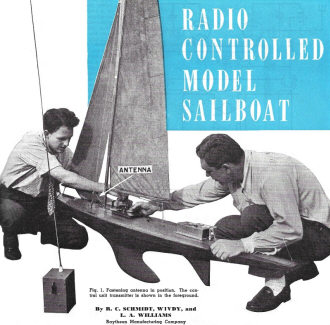
Fig. 1 - Fastening antenna in position. The control unit transmitter
is shown in the foreground.
By R. C. Schmidt, W1VDY, and L. A. Williams
Raytheon Manufacturing Company
Two channel operation, 51 and 53 megacycles, provides complete 180 degree rudder
control.
Simplicity is the keynote in the design of any piece of radio remote control
equipment for model boats or aircraft, because light weight, low battery consumption,
trouble free operation, and low cost, all hinge upon this factor.
In the radio control of the model sailboat described here, the necessary control
operations are solely those of turning the rudder either to left or right at will,
this operation being performed by a small permanent magnet reversible electric motor
and suitable gear train. The remote radio link must, therefore, either carry two
intelligence channels or alternatively, a single channel could be used to alternately
select one and then the other control operation. This "selector" system or single
channel control can be made to accommodate a larger number of control operations.
However, since the operations occur in a fixed sequence, it is at times a very slow
and unwieldy method of control. Also, it is quite common for the receiving equipment
to get out of sequence with the remote transmitter; thus some form of repositioning
of the selector is necessary in the selector system, which usually boils down to
another intelligence channel. For this reason a system was chosen using two separate
radio channels.
The boat used for this experiment is a "Class A" type. The hull is of mahogany
planked construction with a length of 6 ft. and a beam of 14 inches. The single
mast is about 8 ft. in length.
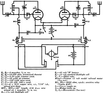
Fig. 2 - Schematic diagram of receiver. Two superregenerative
receivers are used as a means of reversing motor. These receivers operate on different
channels.
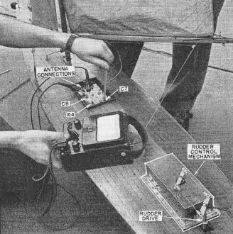
Fig. 3 - Aligning receiver. A 0-5 or a 0-10 milliammeter is clipped
across the open knife switch (S2) for tuning the unit.
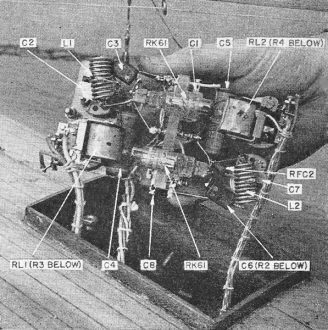
Fig. 4 - Under chassis view of receiver. The two sensitive relays
are mounted atop the metal covers of rheostats R3, R4.
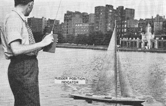
Fig. 5 - "Coming about" - Boston's Back Bay section is the backdrop
for this demonstration. The rudder position indicator should be visible to the operator
at all times.
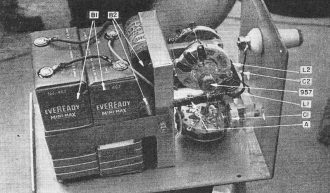
Fig. 6 - Internal view of transmitter control unit. Condensers
C1 and C2 are mounted on a polystyrene bracket supported from the sub chassis by
a metal rod, A.
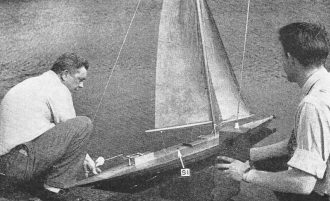
Fig. 7 - Boat carries 500 sq. in. of sail to conform with "Class
A" racing standards.
Receiver
The receiving equipment consists of two single tube receivers using Raytheon
type RK61 tubes operating in the 50-54 mc. amateur band. The RK61 is a subminiature
version of the prewar RK62. This tube operates in a simple superregenerative circuit,
and has a small relay in its plate circuit. Plate current under "the no received
signal" condition is 1.5 ma., and triggers to 0.5 ma. or less depending upon signal
strength. The plate circuit relay must therefore operate within this range of plate
current change. The Sigma model 4F relay usually serves adequately here. This relay
has an 8000 ohm coil, and can be adjusted to operate on as little as 0.2 ma. current
change. With some tubes the optimum relay resistance may be as low as 5000 ohms.
As regards power supply, the RK61 receiver is very economical, requiring only
1.5 volts at 50 ma. each for filament supply, and 45 volts at 1.5 ma. for the plate.
Rudder Control Mechanism
The motor used is a Pittman 12 volt d.c., 6000 r.p.m. model railroad type, which
can be obtained at any hobby craft store. It draws about 0.3 to 0.4 amp. under full
load. In order to assure easy operation, a 3000 to 1 gear reduction was used. In
length of time with the motor operating under load, the rudder may be shifted from
full left to full right in about 15 seconds.
There are many ways of applying this control. The main purpose was to find a
simple, positive, and variable mechanism which would be practically foolproof. The
complete mechanism may be placed under the deck or above deck. The reason for placing
the mechanism above deck in this case was to save hull damage in case of bad operation.
The unit is enclosed in a watertight metal box with all operating parts inside (see
Fig. 3). It was only necessary to drill one hole in the deck to allow for wiring.
Using this method, the rudder can be moved to any position up to 90° left or
right from the neutral or center point.
By the use of 2 microswitches (S3, S4 Fig. 2) for limit
switches the rudder cannot move beyond the 90° position.
Circuit and Construction Details
Fig. 2 includes the circuit of the receiver and associated motor drive for the
rudder. The receivers are mounted on a piece of Lucite which fits flush with the
hatch. The tuning condensers, C2, C7, and plate current adjustment
resistors, R3, R4, are brought out through the top, along
with midget knife switch S2. This switch affords a convenient means of
inserting a 5 or 10 ma. current meter in the plate circuit for tuning purposes.
The photograph of Fig. 4 shows the arrangement of component parts below decks. The
sensitive relays were bolted to the metal back covers of the control rheostats to
conserve space. The RK61's are mounted horizontally in a cradle also made of Lucite,
and are held in place with rubber bands. The tubes have 2 inch tinned leads which
may be used to wire them directly into the circuit if space is at a premium or the
leads may be trimmed to 3/16" and plugged into subminiature tube sockets which are
available. From the tube replacement angle, the use of sockets is better.
Connections from the receiver are cabled and brought to a common terminal board
mounted in the bottom of the hull, as are all the leads from batteries, motor, and
the limit switches on the motor. The limit switches, S3, S4, serve
to open the motor circuit when the rudder has reached the limit of its travel in
either direction.
The transmitter consists of a very simple push-pull oscillator using two 957
acorn tubes with 1.5 volts on the filaments from two paralleled intermediate size
flashlight cells. The plate supply is a pair of 67 1/2 volt "B" batteries of the
type used in portable broadcast radios. The complete transmitter unit is housed
in an aluminum box 4 1/2" x 4 1/2" x 10". The control switch S1, is a
single-gang, 2-circuit, 3-position rotary switch. This switch, when turned to the
left of center, connects the filaments only. When turned to the right of center,
it powers the filaments, and also cuts in the padding condenser, C1 thus
obtaining the second control channel frequency. In the interests of simplicity,
it was decided to switch the filament circuit only for turning the transmitter off
and on to either channel. The short time delay while the tubes are warming is unnoticeable
for practical operation in this type of application. However, a separate filament
switch with S1 in the plate lead would be satisfactory also.
The photo, Fig. 6, is an internal view of the transmitter. A small subchassis
partitions the batteries, and mounts the transmitter circuit components. The 957
sockets are mounted back-to-back and in a vertical position. The condensers, C1
and C2 are mounted on a pillar-supported piece of Lucite, so that they
can be tuned from the top of the transmitter box through two appropriate holes.
The quarter-wave whip antenna plugs into a feedthrough insulator also located in
the top of the box.
In tuning the transmitter, S1 is turned so that C1 is not
connected. Then C2 is tuned to the high frequency-control channel, i.e.,
approximately 53 mc. Then, switching over to the position which includes C1
in the circuit, C1 is tuned for the low frequency channel at 51 mc. It
has been found more convenient to set the transmitter just once, and make subsequent
tuning adjustments on the two receivers. Thus, having once set the transmitter well
within the band, there will be no danger of getting outside of it. Incidentally,
the usual FCC regulations hold in this type of service; a licensed radio amateur
must be present during operation.
Operation
Receiving antennas are formed from an insulated portion of the mainmast stays.
The total length of the receiver antennas should be 46" from the small rods coming
up from each receiver through the hatch cover. Fahnestock clips may be used to connect
the antennas to the rods.
The sensitive relays will probably need some adjustment. The back contact should
be set originally for about 0.025" clearance between the relay armature and the
winding core face. Then adjust the fore contact clearance for about 0.003" or the
thickness of a piece of paper when the relay is open. Then, with the receiver in
operation, vary the adjusting spring tension so that the fore contact closes at
1.4 ma. The plate current of the receiver may be conveniently varied for this test
by means of the plate resistors, R3, R4. If the relay drops
out at less than 1 ma. plate current, the relay contacts are set too wide. Optimum
adjustment of the relay will yield a pull-in current of 1.4 ma., and a drop-out
current of 1.1-1.2 ma.
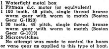
Parts list for rudder control mechanism.
After the preliminary adjustment of the relays, the plate current on each receiver
should be set for 1.5 ma. (3 ma. total "B" battery drain). With no signal, a slight
ragged-sounding audio note of about 600 c.p.s. will be heard from each relay. This
is relay chatter at the 600 c.p.s. super-regenerative quench frequency, and is quite
normal. Turn the transmitter on, and vary C2 of the receiver until the
plate current takes a radical dip. Tune for minimum plate current. Repeat for the
other receiver, using the other transmitter channel. It is always a good idea to
walk the transmitter off 25 or 50 feet and run through a few operations before actually
putting the ship in the water.
No attempt was made to control the boom or vane gear as applied to this type
of boat.
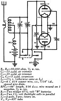
Fig. 8 - Schematic diagram of transmitter - a simple push-pull
oscillator.
Now, just a few words about controlling the boat. In "coming about," apply full
rudder until the limit switch stops the rudder in a full rudder position. The boat
then heads up into the wind. Then, just as the wind carries the mainsheet boom across,
use opposite rudder control to bring the rudder amidships again. After a few hours'
operation the "feel" of the control will allow the operator to time his control
operations nearly perfectly. However, it has been found convenient to put on some
sort of rudder position indicator. This consists of some easily seen mass hung on
a six inch arm to move along with the rudder. Experimentally, we used first a wad
of white cotton, and then a small chromium plated vane. A ping pong ball would be
ideal. With the boat under sail on a specified course, the operator will quickly
recognize his greatest fault - that of over-controlling. Very short pulses of control
time then suffice to keep the boat headed on course.
Variations
A considerable saving in weight is possible by the use of the new mercuric oxide
batteries which should be available in quantity very soon. Also by increasing R3,
R4 to 50,000 ohms, the smaller size 67 1/2 volt "B" battery can replace
the larger 45 volt size. Prospective builders of this equipment should also look
into the possibility of using the new ultra-small and rechargeable wet cells. Also
some small electric motors by Pittman are made for 6 volt operation.
The possibility of using two channels at once should not be overlooked. Referring
to the receiver circuit diagram, (Fig. 2) it will be seen that if both receivers
are operating at once, the motor circuit will not be energized. Thus, if a third
sensitive relay be placed in the "B+" line, and it is adjusted to open at 1.5 ma.
or less, this relay will operate only when both receivers are signaled, but not
when either one alone is. Thus, this third relay affords a third control operation
through the use of only two channels. However, two separate transmitters and transmitting
antennas must then be used.
It is strongly suggested that the model sailboat enthusiast ally himself with
some competent radio amateur rather than try to build his own control equipment,
for though the radio gear is simple as radio gear goes, still the experience factor
in the building and "de-bugging" stages of the project will count for a lot of wasted
time and sleepless nights.
Posted July 30, 2022
|


