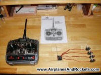
Spektrum DX6 components (also includes charger - receiver battery
not included)
Since Horizon Hobby introduced the Spektrum DX6 spread spectrum radio control
system in mid-2005, it has been a spectacular hit everywhere it is seen. Every review
extols the virtues of a system that is totally immune to interference from both
inband channels and from electrical noise.
Disclaimer: This website is not in any way affiliated with Horizon Hobby, the
distributor for the Spektrum DX6 radio control system. This website's sole purpose
is to promote the exceptional ingenuity and out-of-the-box thinking that went into
creating this system. We owe a debt of gratitude to the folks at Horizon Hobby for
their initiative. They are also responsible for the magnificent
Blade CP helicopter, which I also own.
Attn: There is a newly written section below on the operation of the Cypress
Wireless USB ICs below. Be sure to read it to clear up a lot of questions people
have about the operation of this system!
New Additions
Horizon Hobby sells a capacitor to the receiver that prevent a possible lock-up
condition when high current draw servos are used (as with for a sail for a boat).
Part number
SPM1600, $6.
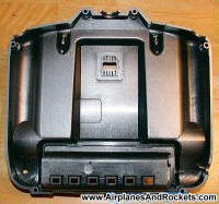
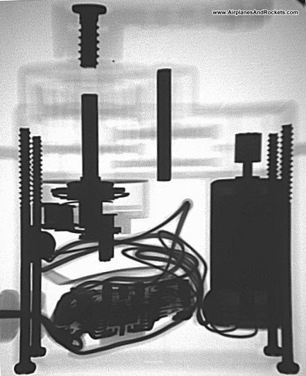
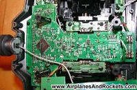
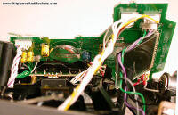
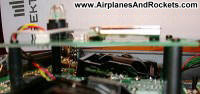
Spektrum DX6 Transmitter (battery compartment)
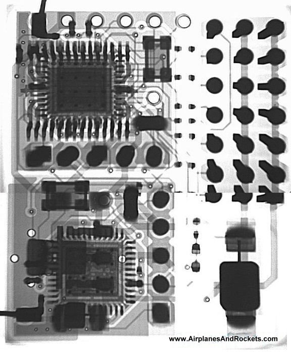
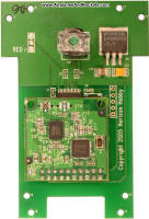
Spektrum DX6 Transmitter (processor PCB)
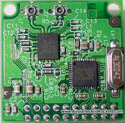
RF PCBs - top
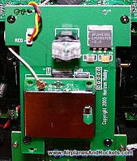
Spektrum DX6 Transmitter (RF PCB - top)
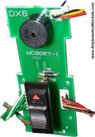
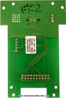
Power Switch PCB
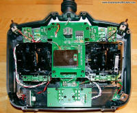
Spektrum DX6 Transmitter (back cover removed)

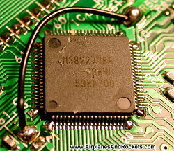
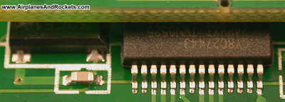
M38227M8A Renesas (Mitsubishi) 8-Bit
Microprocessor w/1kB EPROM
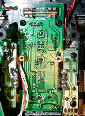
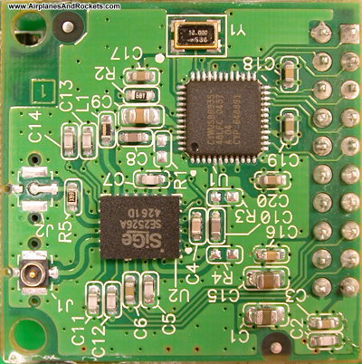
RF PCBs - bottom

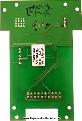
Fuse PCB Under RF PCB

Programming Switches
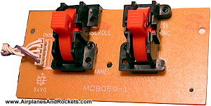
Gimbal Stick & Trim PCB
Fuse PCB (bottom)
This is the version in the FCC qualification report (Horizon
Hobby photo)

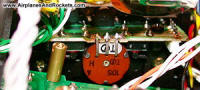
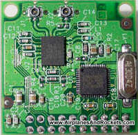
Transmitter RF PCB (shield removed) SiGe
SE2526A PA &
Cypress
CYWUSB6953 WirelessUSB™ PRoC™ Flash Programmable MCU Radio See
CYWUSB6935 datasheet for Radio Portion of CYWUSB6953
CY8C27443 on RF PCB
Spektrum DX6 Transmitter (RF PCB - edge)
Gimbal Centering Mechanism with Stick in Center Position
Gimbal Centering Mechanism with Stick in Center Position
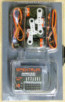
Spektrum DX6 receiver & servos
Click
here for a very cool method for greatly extending the transmitter
operation time by making a simple replacement of the linear regulator with a switching
supply that is a direct solder-in replacement. Compliments of Dimension Engineering.
Click here to download the user's manual. It contains all the programming
information.
If you happen to be an RF engineer or hobbyist, please visit my
RFCafe.com website.
Spektrum DX6 spectrum analyzer display (wide)
Spektrum DX6 spectrum analyzer display (narrow)
What makes the Spektrum DX6 radio control system so unique is that it is the
first commercially available system that, number one, it operates in the unlicensed
2.4 GHz frequency band and, that number two, it employs spread spectrum digital
encoding to effect the control signaling. The 2.4 GHz unlicensed band is one of
several ranges of frequencies that the U.S. Federal Communications Commission (FCC) has reserved for operation of
a class of devices designated as Industrial, Scientific, and Medical (ISM). It happens
to be the band on which the vast majority of computer wireless LANs (WLANs) operate
(IEEE802.11b/c/g/n), as well as all of the available Bluetooth devices. Microwave
ovens, wireless security systems, and a host of other products also run in the 2.4 GHz
band.
So, with all those systems competing for usage in the same bandwidth, why are
there no serious interference problems? The answer is in the spread spectrum encoding-modulation
and demodulation-decoding schemes. Radio systems like the traditional 72 MHz
band versions modulate servo positional information onto carrier tones tuned to
discrete frequencies (pulse-position modulation, PPM, and pulse-coded modulation,
PCM). While the intelligence is digitally encoded, the effect is to cause only a
relatively small deviation in the carrier frequency off of its center frequency.
There are a total of 50 ranging from 72.010 MHz (ch 11) to 72.990 MHz
(ch 60), with 20 kHz (0.020 MHz) spacing between channels. Each transmitter
must be careful not to modulate its signal far enough in to an adjacent channel
to the point that interference is experienced.
In contrast, spread spectrum systems occupy a wide bandwidth (often 1 MHz or
more) and digitally "spread" the encoded signal out across the entire band through
modulation. The digital information is encrypted with a sort of security code that
makes it unique, and the receiver must decrypt the message using the same code.
Depending upon the instantaneous digital code value (millions of possible codes),
the transmitter frequency is tuned (modulated) to a specific frequency within the
allocated band.
Accordingly, there are as many possible frequencies to tune to in the band as
there are digital codes (millions). Since each data bit makes up only a small portion
of the total message, the transmitter broadcasts on each frequency for a short period
of time.
This pseudorandom assignment of frequencies accounts for the "spread" part of
spread spectrum since it spreads the signal over a wide spectrum of frequencies.
In the receiver, the information is demodulated and decoded and the individual bits
are reassembled into a recognizable string of data that is sent to the appropriate
servos (or motor electronic speed controller, ESC).
Additional digital bits are added to the data stream, and are used to enable
the automatic correction of a certain number of missing bits that arrive at the
receiver – this is called error detection and correction. Bits can be missed in
the receiver for many reasons, chief of which are low signal level (separation between
transmitter and receiver too great) and interference from another radio system.
So, if a data stream that is a couple thousand bits long is missing a few valid
bits, the microprocessor can determine what the correct value ("1" or "0") should
be. This is where the spread spectrum scheme provides its immunity to interference.
The probability of two or more transmitters broadcasting a single bit at exactly
the same frequency within the broad bandwidth is extremely low. However, if they
do, then each affected system's receiver is capable of "filling in" the missing
information and the signal gets processed as if no problem existed. Your servos
never get issued incorrect commands.
These Spektrum DX6 transmitter spectrum analyzer plots were made on a
Rohde & Schwarz instrument.
As can be seen, there are two signals, one at 2433 MHz and the other at 2473 MHz,
that are separated by 40 MHz. The signals are sent alternately. Zooming in
on the 2433 MHz signal reveal that it has about a 830 kHz bandwidth. Carrier
suppression is not the greatest as it can be seen protruding above the spread spectrum
waveform in the center. The 2473 MHz signal is similar to the one shown here.
The FCC describes two fundamental types of spread spectrum methods: frequency-hopping
spread spectrum (FHSS) and direct-sequence spread spectrum (DSSS). The Spektrum
DX6 radio control system employs DSSS. The Federal Communications Commission (FCC)
requires all manufacturers of equipment that is capable of generating radio frequency
(RF) energy, whether intentional (a valid signal) or unintentional ("noise"), to
submit products to an approved testing laboratory to validate that they conform
to FCC guidelines. Such products carry an FCC approval identification sticker, and
on the sticker is an FCC ID number.
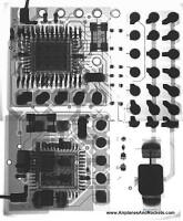
The FCC maintains a public database of all submissions, with great detail as
to the test methods and results, as well as photographs of the inside and outside
of the products. The inside photos are of particular interest, since they usually
provide a pretty good image of the printed circuit boards (PCBs) and in some cases,
enough clarity to make out component part numbers.
Binding
The binding process has been a mystery since it was first introduced. Here are
excerpts from the Spektrum DX6 user's manual:
"Transmitter - When the transmitter is turned on, the system scans the 2.4 GHz
band, finds an open channel and locks on that channel. Next the transmitter scans
for a second open channel and, when found, transmits on that second open channel.
The system is now transmitting simultaneously on two 2.4 GHz channels, giving
two paths of security.
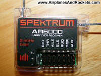
Receiver
Each AR6000 receiver features patented DuaLink (pat pend) technology and is actually
two receivers in one, hence the dual antennas. When turned on, the first receiver
scans the 2.4 GHz band until it finds the specific transmitter's code (called
GUID) that it has been programmed to recognize (see binding page 24) and locks on
that signal. Then the second receiver scans the 2.4 GHz band, finds the second
transmitted code that it's been programmed to recognize and locks on that signal.
This whole process takes less than 5 seconds. The receiver is then locked to that
transmitter via two independent channels, and is virtually immune to model generated
or outside interference."
Keep that in mind while reading the next section.
Cypress CYWUSB6953 & CYWUSB6935 Transceivers
Cypress pulled the full datasheet for the CYWUSB6953 transceiver, which is the
one used in both the transmitter and the receiver, and replaced it with a partial
version. The original had an extensive functional description of the entire chip.
Now, it refers the reader to the datasheet for the CYWUSB6935 transceiver for a
functional description of the RF section. I have included links to both IC datasheets
below (under the photos).
A lot of discussion has taken place about the frequency and operation of the
transmitter. Here is a quote from the datasheet, "The CYWUSB6935 contains a 2.4 GHz
radio transceiver, a GFSK modem, and a dual DSSS reconfigurable baseband. The radio
and baseband are both code- and frequency-agile. Forty-nine spreading codes selected
for optimal performance (Gold codes) are supported across 78, 1 MHz channels
yielding a theoretical spectral capacity of 3822 channels." I guess that settles
it.
The datasheet specifies a maximum output power of 0 dBm (1 mW). However,
the RF PCB of the transmitter has a SiGe SE2526A front-end module, which is described
as follows, "SiGe Semiconductor's SE2526A is a complete RF front end integrating
a high-performance power amplifier, power detector, transmit/receive switch, diversity
switch and harmonic filtering into a compact chip-scale device that is fully matched
to 50ohm. The SE2526A replaces up to 40 components typically required for the RF
front-end, thereby simplifying the design of wireless systems. Unigen's Juno-LPA
modules, based on Cypress Semiconductor Corp's WirelessUSB LR (CYWUSB6935) radio-system-on-a-chip
device and SiGe's SE2526A, are able to transmit and receive wireless signals over
a range up to 1 km." ...and that settles that.
So, what we have here is a basic short-range wireless SoC (System-on-Chip) mated
to a front-end module that has a power amplifier (PA) to boost the output power
for longer ranges, and a built-in antenna switch to route the RF energy either from
the CYWUSB6953 RF Out port through the PA and to the antenna, or from the antenna
to the RF In port on the CYWUSB6953. In doing so, it allows the transmitter to "listen"
for active transmitter channels via its receiver RSS (received signal strength)
function and assign transmit channels on only clear frequencies.
That leaves open the question about exactly how the receiver, which contains
two identical CYWUSB6953 circuits, goes about binding with the transmitter and detecting
the operating frequencies. Does the receiver transmit a low-level signal out to
the transmitter so that the two can arbitrate clear channels of operation? That
possibility was suggested by a person who wrote to me recently (thanks to Mr. Rod
W.). The answer is that I still do not know for certain, but an alternate solution
is proposed next.
From the description given in the user's manual (see excerpt above), it seems
that during the binding process the receiver listens for a special signal from the
transmitter that tells it what the GUID (basically an encoding sequence) of that
transmitter is. The binding operation is separate from the receiver power-up process.
My guess is that all transmitters use a certain channel to send their GUIDs so the
receivers know to always go there to learn them when binding. Then, during power-up,
the two receiver channels use that GUID code when searching for which two frequencies
the transmitter has chosen. In that manner, it is never necessary for the receiver
to broadcast any information back to the transmitter.
Spektrum DX6 AR6000 Receiver (connector side)
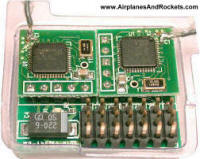
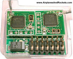
Receiver PCB Assembly
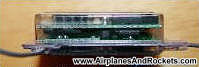
Spektrum DX6 Receiver (edge)
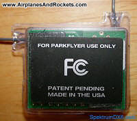
Spektrum DX6 AR6000 Receiver (back side)
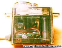
Spektrum DX6 Receiver x-ray
Spektrum DX6 servo

Spektrum servo x-ray
OK, so where do the 4.2 billion possible codes come from? 4.2 billion is roughly
the number of unique codes available in a 32-bit binary system, which is likely
the code length used by the Spektrum DX6, compliments of the Wireless USB IC. Recall
that the IC was originally designed to operate in a very dense RF environment with
data security being a high priority. The more bits that are used to encode data,
the more difficult it is to hack (decode, intercept, pirate, etc.). A lot of data
intercepting schemes rely on brute force processing to basically try every possible
code sequence possible until the correct one is stumbled upon. It takes a long time
to try 4.2 billion codes, even at modern computing speeds. Still, stories have appeared
recently about the relative ease with which the standard 40-bit (1.1 trillion combinations)
encryption on RFID devices can be cracked using just a laptop computer. For another
reference point, the encryption scheme used for the https:// secure websites uses
128 bits, which represents 3.4x10^38 (that's 34 followed by 37 zeros) possible unique
codes.
Transmitter
The Spektrum DX6 transmitter carries an FCC ID number of
R8KUGWR2USXXXX. The hyperlink attached to the FCC ID number is
the page on the FCC website that contains links to all the available documents on
the transmitter. The
internal photographs document shows a wireless spread spectrum
module manufactured by Uniden (Fremont, CA). This is somewhat odd, because it appears
that only the module itself has been qualified, and not the entire transmitter -
which itself has digital circuitry that could radiate unintentionally in excess
of the allowable limits. This module and radio system operates in the 2.4 GHz
Industrial-Scientific-Medicine (ISM) band, which is unlicensed and is the same band
as the wireless LAN (WLAN) products that are used for personal computers.
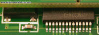
The pictures shown here of the RF PCB removed from my transmitter and the one
submitted to the FCC for the qualification tests are essentially the same. The main
differences are the much smaller crystal oscillator unit and the elimination of
one of the coaxial connectors.
Spektrum AR6000 Receiver
The receiver case is held together with double-sided foam tape attached to the
upper and lower PC boards, and then a little silicon glue at the two antenna exit
points to provide strain relief. Inside, there are two printed circuit boards (PCBs).
One has two duplicate circuits for the spread spectrum receivers and a "motherboard"
that contains the signal decoder and servo drivers. Cypress Semiconductor model
CYWUSB6953 "WirelessUSB™ PRoC™ Flash Programmable MCU Radio" integrated circuits
(ICs) are used (see online
datasheet), along with 13 MHz oscillators. The Cypress IC is capable
of performing both the transmit and the receive function, making it extremely versatile.
There does not appear to be a preamplifier used on the receiver front-end, so
the exceptional range of 1,500 feet or more is provided pretty spectacular. Even
though these types of direct sequence spread spectrum (DSSS) systems in the ISM
band (2.4 GHz), like wireless local networks (WLANs) and Bluetooth systems
are typically advertised for operation over relatively short ranges (300 feet or
so), the range is for a given minimum data rate.
At greater ranges, the error rates increase and more packets of data are lost
and must be resent, or the system data rate must be slowed down. Radio control system
data rates need only be in the tens of kilohertz realm and not in the tens of megahertz
realm, so the operational range is extended. There is a
Factoid
that I wrote for my RF Cafe website that describes the large number of WLAN networks
I was able to detect in a Podunk town in West Virginia, where the houses hosting
the WLAN routers were 100-300 feet away.
According to the datasheet, receive mode current is 61.3 mA. I measured the current
draw of the external Electronic Speed Control (ElectricFly ESC-10) AR6000 receiver
(motor off, servos idle) and got 80.3 mA @ 4.88 V. The current was measured
between the NiMH battery pack (9.6 V, 650 >mAh) and the ESC, and the voltage
was measured across the positive and negative pins of the receiver channel 6 pins.
At some point, I will measure it without the ESC, but for this measurement all I
had on-hand was a 7.2 V Li-Poly battery pack in my
Li'l Poke airplane.
One interesting specification is the electrostatic discharge (ESD) ratings, which
are only 500 V on the RF (antenna) pins and 1,500 V on all other (power
and control) pins. The de facto industry standard for silicon devices is 2,000 V
minimum, with 4,000 V being typically seen. A static charge of 500 V can
easily accumulate on the human body simply by walking across a carpeted floor or
even combing the hair with a plastic comb. If such a charge finds a discharge path
through one of the two antennas, the even could (and likely would) cause a failure
in the IC. Accordingly, extreme care should be exercised to avoid contact with the
ends of the antenna wires. Placing a small dollop of silicon (e.g., tub caulk) on
the ends of the antennas will actually provide a little extra protection since it
will prevent direct contact with the copper wire inside the insulation.
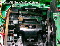
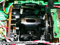
Gimbal Centering
Someone wrote asking about how to convert the left gimbal throttle stick to be
self-centering like the other three axis. Unfortunately, the conversion requires
the installation of both a spring and a plastic lever that rests against two pins
on the stick axis. From what I have read on the forums, getting Horizon Hobby to
provide replacement parts for the Spektrum DX6 system is like trying to get blood
out of a turnip, as the saying goes. It seems everyone has had to come up with a
work-around for broken antennas, cables, and anything else. About the only thing
to do is to remove one of the existing levels and attempts to replicate it in plastic
or metal. It probably would not be really hard to do, but would be time-consuming.
The pictures below are close-ups of the gimbal centering assembly. The top one is
with the stick centered, and the bottom one is with the stick in a maximum deflection
position.
Posted March, 2006
|