|
A long time ago, in a galaxy far,
far away, there existed a modeling civilization that enthusiastically embraced the concept
of building kits for the personal satisfaction of being able to hone craftsmanship skills,
to learn about the make-up of the products being built, and to save money. Radio control
systems were expensive on a per channel basis compared to today's systems. Heathkit,
as it did with a very wide assortment of electronics products, sold a few radio control
systems in kit form. The buyer built everything - transmitter, receiver, and servos.
I do no remember whether the NiCd battery packs came pre-assembled. Note that
Heathkit servos used capacitive feedback rather than resistive (potentiometer). That
idea evidently did not catch on since all modern servos use pots for feedback.
Here is an advertisement for this
Heathkit 3-channel radio
control system from a 1970 issue of American Aircraft Modeler.
Heathkit 3-Channel for Cars, Boats, or Lanier's Hawk Glider
Transmitter is much easier to assemble and RF section comes ready
to use and tuned. Charging is indicated through meter.
Blue Ribbon Review - A Technical Review
Howard McEntee
The Heathkit Model GD-57 control system and this maker's new Spectre car were announced
at the same time and obviously are designed to work together. However, the new three-control
digital system is every bit as applicable to planes and boats, so the Lanier Hawk, an
ARF glider, was chosen as the test aircraft.
Heath has designed a simpler and much lower cost control system, intended more for
the sport modeler rather than for competition fliers. While many parts of the GD-57 system
are similar or identical to those in the much more expensive GD-19 five-control system,
costs have been reduced in ways that do not cheapen the GD-57 system.
Most of the mechanical differences are in the transmitter, which is in the smaller
conventional two-piece case. All small electronic parts except the RF components but
including the charger are on one p.c. board. Paper phenolic is used for this board rather
than the more expensive linen epoxy material.
Control stick assemblies are simple since each stick operates only one potentiometer.
The third control is a small lever projecting from the back of the case (when set near
neutral, this lever sticks out farther than the rubber bumpers on the case back and can
scratch polished surfaces). The RF strip seems quite similar to that in the GD-19 transmitter
but has a different part number.
The GD-57 system also includes a high-grade pencil-tip iron (which handles all jobs
in the system assembly), ample quantities of correct grade solder (small diameter solder
for receiver and servos), a receiver tuning tool and a transmitter antenna wrench. Although
it takes some time, checking over all the system's parts before assembly begins is wise.
If any parts are missing, they can be sent for immediately, and other assembly jobs completed
meantime.
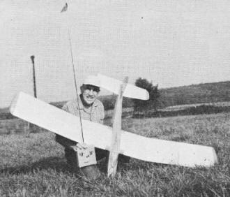
Author with complete project. Lanier Hawk is best suited for slope
soaring or areas of strong thermal lift.

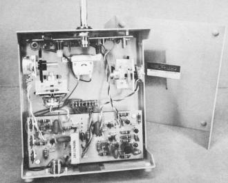
Unique Heath feature is use of ceramic filters instead of IF cans.
This affords sharp alignment without any IF tuning.
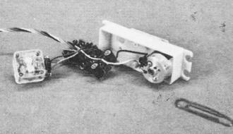
Difficult part of system is servos. Parts must fit close together.
Another feature is capacitive feedback, no wiping contacts.

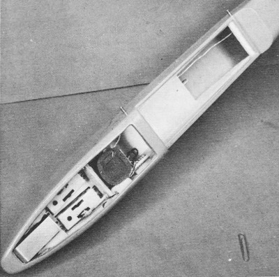
Two-servo installation in Lanier's glider puts all parts as far forward
as possible, but some lead is still needed for balance.
The 130-page instruction manual is comprehensive and covers theory, assembly and tuneup,
trouble-shooting and just about everything else needed. It covers systems on 27, 50 and
72 MHz spots.
When ordering a Heath set, specify the frequency and band desired. While it is fairly
easy to change frequency within a band by using new crystals ($8) and retuning the receiver,
conversion to another band is complicated and expensive, requiring new crystals and new
RF sections, as well as a complete tuning. A change to 50 MHz also requires a new transmitter
front case to allow for the keying button which is pressed to identify the signal at
conclusion of transmissions. A person having a ham license will know what this is all
about.
The charger for both transmitter and receiver nickel-cad packs is in the transmitter,
and the same convenient single charging connector (on bottom of transmitter case) as
in the GD-47 and 19 systems is used. There is no charger bulb. When the transmitter switch
is off, the transmitter meter is put in the charger circuit as an indicator. With switch
on, meter indicates RF output.
This transmitter has the handy fully-collapsible antenna Heath pioneered. Positive
means now prevent the spring clip on the bottom of this antenna from coming off.
In the transmitter, assembly parts are larger and components well spaced-out, but
in the receiver things are considerably tighter. Servos are trickiest to assemble and
are done last. Having assembled the two earlier Heathkit systems, we had no problems
whatever, either mechanical or electronic.
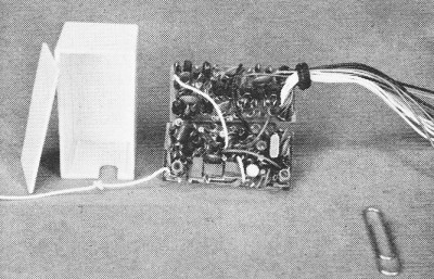
The receiver has two circuit boards, as in the GD-19 receiver, the boards for the
RF section being similar but apparently not identical. Off-register printing on our receiver
made spotting parts locations difficult, but copious drawings and photos in the instruction
book clarified the layout.
The decoder board is quite different from that in the GD-19 receiver. It has only
three controls to handle and uses a pair of transistors for each, rather than the SCS's
in the GD-19. The two boards are mounted one above the other, resulting in a receiver
measuring 1 5/32 x 1 3/16 x 2 1/4" and weighing 2.15 oz., including the cables and connectors.
When the receiver is completed, a resistor may be left over. It will be 2700 ohms if
the outfit is on 27 MHz, 470 ohms if on 50 or 72 MHz. Apparently both resistors are packed
with every receiver.
The two GD-57 servos are identical to late model GD-19 servos and are interchangeable
(connector pin diameters did seem a bit different, but not enough to prevent easy interchange).
Early GD-19 servos, by the addition of one resistor, can be made the same as later-model
GD-19 and all GD-57 servos. (When the early servos are driven fully one way, they bounce
a bit before stopping.)
The resistor can be fitted with little trouble and is included in all later Heathkit
servos. There is no bounce when they are driven to the other extreme. This bounce is
hardly noticeable if the servos are loaded with a linkage and control surface, but it
is worth mentioning.
Current drain from the 500 maH, 9.6V transmitter pack is about 100 ma, while the receiver
draws 6 ma from its center-tapped 4.8V, 500 maH pack. The latter weighed 4.2 oz. with
connector. Servos idle at around 2 ma not moving; current can rise to as much as 350
ma if they are stalled. They weigh 2.52 oz. each with connector. Total transmitter weight
is 2 lb.
Quick frequency change within the 27 MHz is convenient and often mandatory in some
types of competition (pylon racing, RC car racing, etc.) For car work, Ed Sweeney and
Fred Marks have described a simple method for quick frequency change. The required crystals
for transmitter and receiver should be purchased from Heath in matched pairs (use parts
numbers from the instruction manual). Also buy a Motorola integrated circuit socket of
the long rectangular style.
Cut off a section across this socket and solder it to the transmitter p.c. board where
the crystal has been removed. (A hole could be cut in the case top and the new crystal
socket placed on the present underside of the p.c. board. Thus crystals could be changed
without opening the transmitter case.) Cut off another section of the Motorola socket
and solder it in the appropriate location on the underside of the receiving p.c. board.
Then turn the board around in the case and cut a slot in it so the crystal may be inserted
from the outside.
For RC car purposes (where ranges are rather short) no retuning of either transmitter
or receiver is required to operate on any of the five available 27 MHz RC spots. Both
crystals must be prevented from coming loose due to vibration, handling, etc. A simple
strip of sticky tape should do the job. Code each crystal with colored dope to match
the frequency, making sure the code clearly indicates which crystal is for transmitter,
which for receiver.
Our experience in building the GD-57 system has been excellent and its operation in
a Heathkit Spectre and in the Lanier Hawk glider, reliable. This certainly seems a fine
system for the sport plane flier or for competition RC uses which can be handled with
a maximum of three controls. By following the book carefully, it really is hard to go
wrong. Construction time was a bit over 18 hours for the transmitter, the receiver, battery
and switch harness, and two servos. This includes tuneup and adjustments.
The Hawk Glider
Plastic planes are considered by some to be completely expendable, thus not worth
anything but the most rapid and slipshod assembly job. We disagree. Even if the plane
itself is expendable, the radio certainly is not. Therefore, it is as important to use
as much care with these ARF jobs as with a prized original.
The Hawk is quite similar to Lanier's earlier Eagle glider. The main difference is
the Hawk's nose, which is considerably longer by some four inches. This makes for better
appearance and takes less lead to balance (but plenty is still needed). Scanty instructions
might indicate that the Hawk was intended for the experienced builder, rather than the
glider novice who wants to try this mode of RC with a minimum expenditure of time and
money. However, the following discussion should clarify construction details.
An engine mount inside the nose compartment is shown, but it makes it difficult to
fuel-proof the plywood frame which strengthens the inside of the fuselage. Keeping fuel
away from the radio equipment would be difficult and fuel residue would quickly make
a real mess of the uncovered foam wing and stab.
Lanier recommends using high start, which we strongly endorse. (Slope flying really
would be the best for this heavy craft.) The wing seemed to take high-start launches
fine. Full-length 3-ply spars in the wing panels are 7/8 x 1/8".
Wing surfaces were sanded with fine paper before assembly. Trial assembly with the
dihedral braces showed a 3/16" mismatch between the three panels at each joint, so the
edges were sanded to remedy this. Wing dihedral is not specified. We blocked up the tips
5 1/2" at the tip undersurfaces and this seemed ideal.
Instructions suggest attaching the wing tips and the LE and TE center plastic doublers
with narrow strips of Air-O-Sheet. This may be a quick method, but epoxy is much more
reliable. Being dubious of the Air-O-Cement stab fuselage joint, we fitted four Air-O-Sheet
angles under the stab instead of two.
The raised top over the stab must be cut out to insert the fin, necessitating a slot
of about 4 1/4" long by 1/2" wide at its widest part. Trim the edges so the fin will
fit flush against them. Then trim the fin bottom edges so they conform to the stab top
and the fuselage top.
A small piece of 1/8" ply is furnished for a stub spar inside the fin. This piece
was too narrow to spread the fin sides against the raised fuselage cutout edges (close
contact is needed if the Air-O-Cement is to hold at all). A piece of firm 1/4" thick
balsa, cut to fit here, was also contoured on the underside for a reasonable fit on the
stab top. This piece was epoxied into the fin and against the stab top.
When dry, Air-O-Cement sealed the fuse-fin edges, and a fillet of Aero-Gloss model
cement joined the LE of the fin to fuselage top. This may seem like a lot of fuss, but
the joint has held firm through some horrendous cartwheel landings in gusty wind!
A standard rudder horn was used with a small block of balsa cemented inside the rudder
to take the compression of fastening bolts.
The sheet plastic area under the wing was cut out to determine what kind of a compartment
it would afford for the radio. The cutout sheet contributes considerable stiffness to
the fuselage torsionwise and, after the pushrods were installed, it was replaced. Servos
were located as far forward as possible for good balance.
For the Heathkit servos, slots 1 x 2 3/4" were cut in the ply nose platform. Four
corner holes were drilled for each, then the ply was removed with a Moto-Tool and various
cutters. Servos are held by #2 x 1/2" wood screws through the grommets.
The Sullivan GoldN-Rods pushrod casings are held in slots near the tail and to the
plywood just above the rear rubber pegs with Goo. Casings should be roughened first.
Their forward ends are held in the ply with aluminum nuts.
The linear output of the elevator servo is fine, since elevator movement need be only
3/8" up and down. Wide rudder movement is required for most gliders, and the Hawk is
no exception. The original link from linear servo output lug to the innermost hole of
a Midwest horn gave about 1 1/4" rudder movement to each side, which is not enough. Alternatives
are to use a shorter horn or use the rotary bar servo output. Rudder movement should
be at least 1 1/2" each way.
A tow hook must be added to the Hawk skid, which has a cutout area at the right point.
Ours was bent of soft 0.050" aluminum sheet. It is held to the skid by two #4 bolts.
To get the receiver as far forward as possible, 5/8" of the vertical ply just to the
rear of the piece holding the pushrod ends was cut away. The receiver is wrapped in foam
plastic and set vertically in the fuselage.
Battery pack placement was a problem. By removing the case from the Heath flatpack,
rearranging the cells in a two-over-two shape, and repackaging with plastic electrical
tape, the new square pack goes neatly in the Hawk nose, just ahead of the servos.
Hawk instructions casually mention needing about 8 oz. of lead for plane balance!
However, with the radio as far forward as possible, about 6 1/2 oz. was needed (with
wing and fuselage top cover in place). Lead in the form of two horizontal U-shaped pieces
was installed in the nose, using plenty of epoxy. The plane should balance at the wing
spar, about 3" in back of wing LE.
Final job is fitting the fuselage cover over the nose compartment and wing and then
adding the canopy to this piece. The cover needs to be trimmed drastically to fit over
the wing. Apparently the cover is intended to be held by the wing rubbers, but it was
best to put an extra band across the cover between the rear rubber pegs. Instructions
specify small sheet-metal screws to attach the cover at fuselage nose. However, in any
landing where the wing is pulled loose, the screws can be torn out; sticky tape would
be better.
Aside from many hand glides to get the feel, all serious flying was done on a high
start (the Soarplane version mentioned in Hawk instructions). The glider towed aloft
nicely but, because of its weight, some wind would have helped. Once off the towhook
the Hawk has a reasonable glide angle, but it's no Cirrus! The wing loading explains
why. Our Hawk weighed 68 oz. and useful wing area (excluding covered center area) is
about 4.87 sq. ft. - a loading of about 14 oz./sq. ft. Many current high-performance
gliders run 10 oz. per sq. ft. or under. We feel the Hawk would do best in slope soaring.
Other improvements might be suggested. Lightweight RC equipment is no advantage since
weight is needed in the nose anyhow. Larger diameter wing rubber pegs are needed because
in a ground loop the wing rubbers often did not pull off the pegs, but the wing rotated
far enough to pull the rubber off the rear doubler and onto the foam, which tore. Rubber
pegs should be at least as large in diameter as the heads of the holding screws.
The rear wing doubler should be twice as long to prevent foam damage by the rubbers
in a ground loop or cartwheel. Again, when the wing is knocked askew, the fuselage area
just behind and above it takes a real beating and should be strengthened.
Strips of Air-O-Skin on the wing TE would help prevent handling dents and digs. If
the ply shelf in the nose area were extended 5/8" by moving the bulkhead back, it would
allow more space for the larger servos; if the forward end of this shelf were dropped
1/4" it would make battery installation much simpler.
Posted July 7, 2018
|