|
A couple years ago I experimented
with adding rudder control to my
Comet Sparky via a radio control system salvaged from an Estes Sky Ranger model.
It used a solenoid actuator mounted on the vertical fin, and the receiver mounted
in the cabin area of the fuselage. A single cell LiPo battery provided power. To
save weight I stripped the components that came with the receiver for motor control.
It worked kind of OK, but the actuator really wasn't powerful enough to more the
rather large rudder with any authority. I vowed to make it better, but have not
had the opportunity. This article from the September/October 1965 edition
of American modeler proves that the idea has been around for a long time. Even in
1965 people were lamenting the disappearance of wide-open spaces for flying free
flight models (unless you live in the Midwest or Southwest deserts). Mr. Phillips'
airborne system boasted a mere 1.3 ounces - a ton by today's standards, but quite
an accomplishment 50 years ago. He even included plans to a custom airplane model
to host the equipment. NASA Engineer Develops Servo-Tab Control
for Rubber-Powered R/C
By W. Hewitt Phillips
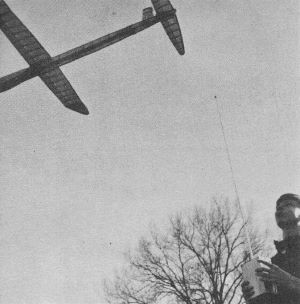 The author's son brings model down by gliding
it in circles overhead. No chase!
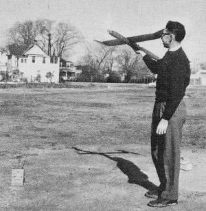 Solo launching technique demonstrated by
Mr. Phillips. Let the model lift off and then you can take up the transmitter. All
radio flying should be like this!
Many of the old-timers agree that the greatest thrill in modeling is to have
a rubber-powered plane spiral up, hook a thermal and soar off, leading the builder
on a merry cross-country chase, unfortunately, this kind of flying requires the
wide, open spaces, which are rapidly disappearing. Even the use of dethermalizers
and the 3-minute or 5-minute max has not helped the situation much. In a 10-mph
wind, a model flying in neat circles will drift one-half mile in three minutes.
How many city dwellers have a half-mile stretch of field available? And then, there
are always times when the model will head straight down wind. The author
has always dreamed of being able to control one of these high-performance rubber-powered
jobs to keep it flying overhead. With an air-speed of 12 to 15-mph, the average
Wakefield-type or unlimited category rubber-powered model will make headway into
the breeze on any reasonably calm day. Recently, developments in radio control have
progressed to a point where this type of control is practical. As a result, the
local playground can become a flying field. All that is needed is a radio
installation, including batteries, receiver and actuator, weighing less than about
1 1/2 oz. Fortunately, miniature transistorized receivers weighing 3/4-oz or less
are readily available in inexpensive kit form. A pair of the smallest size pen cells
(Eveready No. 912 or equivalent) weighs just under 1/2-oz. These weights leave just
1/4-oz for the actuator. In this article, an actuator weighing less than .07-oz
is described! How can an actuator weighing .07-oz control a model of 3 to
4-ft span? The secret is the use of an old idea from full-scale aircraft, the servo-tab
control. This device was patented in 1922 by
Anton
Flettner, the German, who also invented the rotorship. For this reason, the
device is sometimes called a Flettner tab. As early as 1925, this tab control was
used on airplanes such as a huge old Handley-Page bomber when pilots found that
the barn-door sized rudders were too heavy to move by human muscle power alone.
Today, airplanes such as the DC-6, the Boeing 707 and the DC-8 use servo-tab controls
so that the pilot can move the controls with comfortable forces when flying along
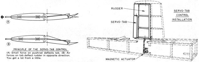
at 300 to 600-mph. The principle of the servo-tab control is that the pilot
(or in the case of a model, the actuator) is connected to a small tab on the trailing
edge of the control surface. As the tab moves, air forces developed on the tab push
the control surface in the opposite direction. Because the tab is so small, it can
be moved with extremely small force. To control a rubber-powered model a
small magnetic actuator, similar in principle to a relay, is connected directly
to the tab control horn by a push-rod. Normally, the tab is held full left by a
small spring, producing right rudder in flight. On transmission of a solid signal,
the actuator pulls the tab full right, producing left rudder. For neutral, a pulsed
signal with equal on and off periods may be used. In practice, however, it is found
that full control in one direction or the other is used most of the time anyway,
so that quite satisfactory control can be obtained with a simple on-off pushbutton
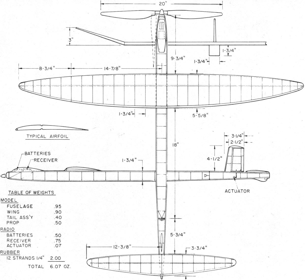
on the transmitter. The rubber-powered model used by the author for the
radio-control installation is fairly conventional. Its design, therefore, is not
emphasized in this article. Instead, the control installation is described in detail.
A three-view drawing of the model and a table of weights is shown. Any conventional
rubber-powered model of this size could readily be converted to R/C by the method
described. The radio receiver and batteries are mounted on top of the fuselage
near the nose in order to move the center of gravity as far forward as possible.
To save the weight of a battery box, the batteries are attached with Scotch Tape
and wired by soldering hookup wire to make the connections. A flea clip is used
as a switch. The magnetic actuator is so light that it may be mounted back in the
tail, eliminating the need for long control linkages which would add friction and
interfere with the rubber motor. To get the power to the actuator, a pair of strands
of No. 40 magnet wire are run from the back along the length of the fuselage. These
wires are preferably glued to the longerons before the fuselage is covered, but
they may be attached on the outside with a coat of dope if it is desired to convert
a completed model to R/C. A pair of light contacts made from bits of brass are soldered
to the wires and glued to the ends of the longerons to make contact with a similar
pair of contacts soldered to the wires in the removable tail section. The No. 40
magnet wire, .003 inches in diameter (almost as thin as a human hair), adds no appreciable
weight to the model, yet has very low resistance compared to the actuator coil itself.
Ordinary hookup wire would be prohibitively heavy for this installation.
 (above and below) Practical, inexpensive radio
control of rubber-powered planes is now possible by a system consisting of batteries,
receiver and actuator which weight less than 1.3 oz. Enjoy sport flying from small
fields. Interesting new contest events are proposed.
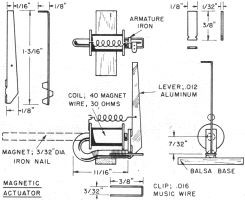
Details of construction of the actuator, tab and linkage are now described. The
small magnetic actuator used to operate the tab is shown. The small electromagnet
may be made by winding wire on a nail of 3/32 inch diameter. The nail should first
be heated to red heat and allowed to cool slowly to soften the iron. Fit celluloid
or cardboard end plates and wind with No. 40 magnet wire, using a hand drill, to
a depth of about 1/16" along a length of 3/8". About 35-ft of the fine wire will.
be required. Finally, bend the back part of the nail around to a U-shape and file
the ends square. The coil should have a resistance of 30 to 35-ohms. The
U-shaped magnet, when energized, attracts a small piece of iron, or armature, in
a manner similar to a relay. Instead of using this armature to operate contacts,
however, it is attached to a light aluminum lever about 1 1/4" long which serves
to magnify the motion. The armature may be made from a piece of soft iron 1/32"
x 1/8" x 3/8". If sheet iron cannot be obtained, a piece of a nail filed flat on
one side may be used. The aluminum extension is attached by binding with nylon thread
and gluing with model cement. Soft .012" sheet aluminum suitable for this and other
aluminum parts in the control system may be obtained from hardware stores in the
form of aluminum flashing. A small clip of .016" music wire keeps the armature in
place as shown. The armature should be a loose fit in the clip. The armature may
be inserted or removed by turning it 90° inside the clip. A small spring, made from
.006" music wire, tends to keep the armature against the magnet. This spring is
mounted oppositely from the spring found in an ordinary relay, which tends to keep
the armature away from magnet. In the present arrangement, the armature is held
away from the magnet by the tab return spring. This return spring overpowers the
spring on the armature. The two springs working against each other serve to take
up any backlash in the tab linkage and hold the armature in the correct position.
If .006 music wire is hard to obtain a piece of 1/32" rubber may be substituted
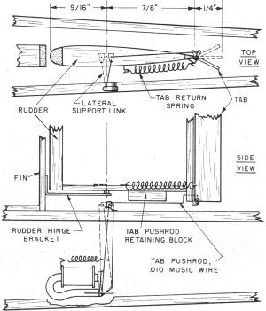
for the spring. The method of hooking up the actuator to the tab and rudder
is shown. A most important detail is the location of the end of the actuator arm
which moves the tab pushrod. With the tab in neutral, this arm must be directly
below the rudder hinge line. With this setup, movement of the rudder will not affect
the tab angle. Full travel of the actuator arm is about 1/16 inch. This motion is
shown exaggerated for clarity. In order to get adequate tab travel of plus and minus
30°, the tab control horn must be quite short, about 1/16". Though the design
of a model for R/C conversion is not critical, some attention must be paid to the
details of the vertical tail and rudder design. The tail size can be quite small
because the radio receiver installation in the nose moves the center of gravity
farther forward than usual. The rudder should be aerodynamically balanced. In other
words, some rudder area should be located ahead of the rudder hinge line to reduce
the moment required to deflect the rudder. In this way, the tab size required to
deflect the rudder may be reduced. Experiments have shown that the location of the
hinge line should be at 1/3 the total rudder chord. A tab chord of 15% of the total
rudder chord and a tab span of 2/3 of the rudder span have proved satisfactory.
Stops should be placed on the fuselage to limit the rudder motion to plus and minus
25°. The rudder, tab and all linkages must be perfectly free from friction.
They should be so free that when the model is tilted from side to side, with the
pushrod disconnected, the tab and rudder will readily flop back and forth due to
their own weight. Once the importance of this low friction is realized, it is not
so hard to obtain as might be thought. Rather than use thread or cloth hinges, common
in most R/C model practice, hinges should be made with .010" music wire shafts fitting
in holes punched in .012" sheet aluminum. Drilling the holes is quite unnecessary.
The holes for the bearings may be punched in with common pins. Small bushings or
washers to separate the moving parts may be made by stripping a short length of
plastic insulation from hookup wire and slicing it into 1/32" lengths with a razor
blade. Care must be taken when covering and doping the model to avoid getting any
dope, paper fibers or glue strings into the "works" to add friction. The
tab is made of 1/32" sheet balsa. Small pieces of .012" sheet aluminum, with holes
punched in them with a common pin, are used as bearings at the top and bottom. The
lower bearing is made integral with the tab horn. The two holes, one for the tab
pushrod and the other for the lower tab bearing, should be 1/16" apart. A small
hook is attached to the tab even with the lower rudder rib to hold the tab return
spring. This spring may be made of .006 music wire or a 1/32" rubber strand may
be substituted. The rudder is of conventional built-up construction. The
tab and rudder hinges should be installed before covering the rudder.
The pushrod to operate the tab is made from .010" music wire. This
size may sound pretty small to conventional R/C builders, but it is plenty strong
for this application and the small diameter contributes to low friction. Pinholes
punched in the tab horn and in the actuator lever to act as bearings can be a sloppy
fit because the springs on the tab and actuator keep the linkage preloaded, thereby
taking up the backlash. The pushrod is simply slipped in place and retained by a
light balsa block glued to the bottom of the rudder. A U-shaped bend in the tab
push-rod will allow adjustments in its length to get exactly the tab motion desired.
The limit of tab motion when the actuator is energized is provided by the
armature hitting the actuator magnet. A thin coat of glue or dope should be applied
to the armature to prevent actual metal-to-metal contact between the two parts,
to prevent them from sticking due to residual magnetism. The limit of tab motion
in the opposite direction is provided by a stop which bears against the hook holding
the tab return spring. An additional wire link, the lateral support link,
is shown. The purpose of this link is to keep the top of the actuator lever from
moving sideways. This link is desirable because the clip at the bottom of the relay
armature does not restrain this lever very effectively against lateral motion.
A careful adjustment and checkout of the completed installation should be
made before attempting a flight. First, the tab pushrod should be adjusted in length
so that, when the magnet coil is energized, the tab deflection is 30° left. No other
travel adjustments are necessary since a stop on the tab limits the deflection to
30° right when the magnet is not energized. The linkage design determines the separation
of the armature from the upper magnet pole when the magnet is not energized. This
separation is about 1/64 inch. This value should not be exceeded, as the ability
of the magnet to "pull in" the armature decreases rapidly as the separation in-creases.
Next, the spring tension on the tab return spring should be adjusted. As
a rough guide or as a starting point for the adjustment, the spring tension may
be balanced against a small weight as follows: Temporarily glue a piece of 1/32"
square balsa, 2 inches long, to the tab to act as a lever for hanging a small weight.
Cut out a piece of the .012" aluminum 1/8" wide and 1/2" long. Lay the tail on its
side and hang this piece of aluminum (about .002 ounces) over the lever. With the
weight 1" from the tab hinge line, the tab should just move to its neutral position
against the tension provided by the combination of armature spring and tab return
spring. Now connect a pair of flashlight batteries producing 3 volts to
the magnet coil. The pull of the magnet should snap the tab to the full-left position.
For a final adjustment of the spring tension, reduce the voltage gradually to 2
volts. The tab should not cease to operate until the voltage drops below about 2
volts. With this setting, the control will continue to function as long as the
battery voltage is sufficient to operate the receiver. A final check of
the completed installation can be performed by holding the rudder in neutral with
a piece of Scotch Tape and keying the transmitter on and off. The tab should snap
smartly from side to side. With the rudder free, the rudder motion will be random,
but in flight the air forces will cause the rudder to flip over instantly when the
tab moves. The procedure for flight adjustment of the model is very similar
to that for any conventional rubber-powered job. Particular care should be taken
to adjust the model to fly straight with rudder in neutral, both power on and in
the glide. In this way, equal control effectiveness for left and right turns will
be available at all times. First, tape the rudder and tab in neutral and check the
glide. If any turn is noted, correct it by warping the wing slightly. Then adjust
for straight flight under power by varying the amount of side thrust. Since
launching a rubber-powered model requires both hands, solo launches present a problem.
The author has found that a satisfactory procedure is to set the transmitter on
the ground, launch the model, then quickly pick up the transmitter and take control
as required. Control of the model in flight comes naturally with a little practice.
A flyer accustomed to gas-powered radio-control jobs will consider the model docile
because of its low speed. To the rubber-powered fan, however, this means of control
offers a world of exciting possibilities. The model may be steered into thermals,
allowed to hang in them or drop out as desired, and be brought down to spot landings.
All this can be done in a field no larger than the average playground. Because
the current drain of the actuator is very small (about 100 milliamps for a 30-ohm
coil) a pair of the smallest pen cells will last for a whole day's flying. To get
a little extra boost in model performance, these pen cells may be sawed in half,
using a jeweler's saw, and the ends covered with a double layer of Saran Wrap bound
on with nylon thread to keep the moisture from evaporating. These half-size cells
weigh only 1/4-oz per pair and still give enough energy for about five flights.
One of the more interesting aspects of the rubber-powered R/C model is its
contest possibilities. These models should not be flown in competition with uncontrolled
models. Such a procedure is certainly contrary to the spirit of the present AMA
rules, even if it is not specifically prohibited. Instead, the rubber-powered R/C
model offers the opportunity for a special type of contest in which all artificial
design restrictions and limitations are removed, and in which the element of luck
is greatly reduced. Consider, for example, a contest for rubber-powered
R/C models in which the rules are as follows: (A) Winner determined by the maximum
endurance (best of three attempts); (B) Flight disqualified if the model fails to
land in a specified 100-ft radius circle. The usual artificial restrictions
such as weight rules or limitations on maximum endurance are completely absent.
A review of the history of outdoor rubber-powered model development shows that in
the early days no restrictions of any kind were imposed, but primitive design and
construction techniques prevented unduly long flights or loss of many models. As
models improved, however, weight rules were imposed, first 1-oz per 50 square inches
and then 2-oz per fifty square inches. This restriction failed to hold endurance
in bounds for very long, but it did end the incentive to make structurally light
models. Finally, as dethermalizers were perfected, the max concept was introduced.
This rule has the objective of preventing out-of-sight flights. As the model designs
improved, the ability of more and more modelers to make maxes as a matter of course
has resulted in all experienced builders being placed on more or less equal terms.
The natural result is more rounds and more flyoffs, until the contest is decided
partly by physical endurance of the modeler and, in some cases, by luck.
How does radio control change this situation? With contest rules of the type
proposed previously, there is no need for the max restriction. The flyer must bring
the model in to a landing near the launch point and is thereby prevented from losing
it. In addition, there is no need for any weight rules, because the wing loading
must be kept high enough for the model to make headway into the wind and because
the radio gear provides an unavoidable "payload" weight. Skill in flying becomes
important, because the model can be allowed to circle in a thermal for a while,
but can never be allowed to drift downwind so far that it cannot glide back to the
launch point. Since thermals do drift with the wind, very long flights are unlikely.
If more emphasis on precision of flying is desired, the rules suggested
previously might be modified such that the endurance in seconds is decreased by
the distance in feet that the model lands from the launch point. With rules such
as these, the modeler is faced with a true test of skill in designing, building
and flying. He may gain an advantage by better aerodynamic or structural design,
more sophisticated or lighter control equipment, and by skill in riding the air
currents. He is no longer placed on a common level with other builders by artificially
imposed restrictions.

Plans for Rubber-Powered R/C Model Airplanes
<click for larger version>
Posted November 13, 2011
|