|
G. Harry Stine was
(and in some places still is) a household word
(ok, a letter and two words) amongst people who engage
in model rocketry. As a degreed physicist, he spent his professional years
working in both civilian and government aerospace projects. In his spare time, Mr. Stine
contributed mightily to the science, industry, and sport of model rocketry. His
monthly columns in American Aircraft Modeler magazine were read and appreciated by enthusiasts
hungry for a regular helping of the technical side of the craft, served in layman's
terms. A typical article written by him reports on some happenings in the trade
show and contest realms, while including a lesson in model rocket design and flight.
Countdown: Low-Drag Design
 Centuri Engineering displayed a variety
of designs at the recent California MATS. Left to right: Defender, T-Bird, Micro-Probe,
Astrobee-350 semi-scale, Chuter-2, Arcon, Recruiter, Bat-Rock, Jaguar, Honest John,
Javelin, IRIS and Snipe Hunter. Centuri Engineering displayed a variety
of designs at the recent California MATS. Left to right: Defender, T-Bird, Micro-Probe,
Astrobee-350 semi-scale, Chuter-2, Arcon, Recruiter, Bat-Rock, Jaguar, Honest John,
Javelin, IRIS and Snipe Hunter.
Defined are two major design areas that affect aerodynamic drag as: shape and
finish. Author asks the questions and supplies the answers too!
G. Harry Stine
Three major forces act upon a model rocket in flight: motor thrust, gravity and
aerodynamic drag. You can select motor thrust force to some extent by choosing the
proper model rocket motor; motor thrust acts on a model for only a short period
of time during the flight. You can't do anything about gravity ... yet. It's there,
always acting to retard the vertical flight.
But there is something that you, a model rocket builder, can do to reduce the
forces of aerodynamic drag. Drag forces can be quite high, as you can attest if
you've had a well-glued fin come off in flight!
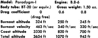
 To give some idea of the magnitude of these
drag forces, I've calculated the theoretical performance of a hypothetical model
rocket, the Paradygm-I, with zero drag and with two different drag coefficients.
Performance values are shown in the table. The flight-with-drag calculations were
made from the Malewicki Report (Estes TR-10). Paradygm-I is a reasonably typical
model rocket, and the two drag coefficients, 0.6 and 0.8, are typical of those which
actually exist in the models that we fly. For a basic discussion of drag coefficient,
refer to "Handbook of Model Rocketry." The two coefficients, 0.6 and 0.8, can be
the difference between a well-made, well-designed model rocket and a model that
is just slapped together with no attention to drag reduction. To give some idea of the magnitude of these
drag forces, I've calculated the theoretical performance of a hypothetical model
rocket, the Paradygm-I, with zero drag and with two different drag coefficients.
Performance values are shown in the table. The flight-with-drag calculations were
made from the Malewicki Report (Estes TR-10). Paradygm-I is a reasonably typical
model rocket, and the two drag coefficients, 0.6 and 0.8, are typical of those which
actually exist in the models that we fly. For a basic discussion of drag coefficient,
refer to "Handbook of Model Rocketry." The two coefficients, 0.6 and 0.8, can be
the difference between a well-made, well-designed model rocket and a model that
is just slapped together with no attention to drag reduction.
The figures speak for themselves. The differences between burnout velocities
is significant, whereas the wide variation in total altitude is striking. The best
streamlining permits a maximum altitude that is only some 30% of the zero-drag potential
altitude, while the higher-drag example is about 26% of the zero-drag.
Don't knock the 4% difference between the two drag examples; it often wins contests!
There is 125 ft. of difference in peak altitude, about 12%!
It should be obvious from this hypo-thetical example that you can achieve significantly
better performance if a mod-el has lower aerodynamic drag.
 I ran out an extension of the Paradygm-I
example to investigate effects of small changes of weight due to more paint or getting
a better finish. Strangely enough, a model of the Paradygm-I is less sensitive to
weight changes than it is to an improved drag coefficient! Another 0.1 to 0.2 oz.
of model weight affects the final altitude a lot less than a change in drag due
to better streamlining and finish! Check this for yourself. The small amount of
extra weight added by a better finish or improved aerodynamic shape pays off handsomely
in performance. I ran out an extension of the Paradygm-I
example to investigate effects of small changes of weight due to more paint or getting
a better finish. Strangely enough, a model of the Paradygm-I is less sensitive to
weight changes than it is to an improved drag coefficient! Another 0.1 to 0.2 oz.
of model weight affects the final altitude a lot less than a change in drag due
to better streamlining and finish! Check this for yourself. The small amount of
extra weight added by a better finish or improved aerodynamic shape pays off handsomely
in performance.
Later, when I can get proper charts and graphs drawn up, we'll discuss the "why"
of improved aerodynamic drag. Our discussion now will be confined to the "how" of
reducing aerodynamic drag. Some of the "why" can be found in the "Handbook" for
those of you who are impatient.
There are two major areas of design and construction that affect aerodynamic
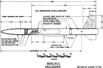
drag: 1) shape,2) surface finish. To illustrate, I've designed the Morlin-I. Drawings
and dimensions appear here. This is a competition payload model. It could have been
a simple altitude competition model, too (it still can be if you eliminate the payload
section, hollow balsa plug, etc. and make the body tube the same length as the sum
of the payload shroud and original body tube length). Morlin-I would make a good
model for the new NAR Quadrathon Competition that requires an entry be flown in
Class 1 Altitude, PeeWee Payload, Streamer Spot Landing, and Class 1 Parachute Duration
with no changes except in the recovery device. Yes, Morlin-I is based upon Talley
Guill's Dubnica Payloader but is a considerable improvement over the Talley Bird
- it's two design generations removed, as a matter of fact.
Nose Shape: There are two forms of aerodynamic drag affecting the nose of a subsonic
model rocket in flight: pressure drag and friction drag.
Nose shapes having the lowest pressure drag are, in order of increasing pressure
drag coefficient: ellipsoidal, ogival, and hemispherical - with very little difference
between the last two.
Friction drag on the nose depends upon the total surface area (called "wetted
area" in aerodynamic parlance) and the surface smoothness.
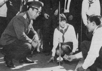
Cosmonaut Pavel Romanovich Popovich received a briefing from
two Yugoslav Young Pioneers at the 18th Int. Astronautical Fed. Congress held September
1967 in Belgrade.
The best compromise between pressure drag and friction drag coefficients of an
ellipsoidal or ogival nose shape is a length-to-base-diameter ratio between 2 and
3. Morlin-I has a hollowed-balsa ellipsoidal nose with an l/d ratio of 3. This gives
a pressure drag coefficient so low that it's difficult to measure it. If the balsa
surface is filled and a very smooth, high-gloss finish applied, the boundary layer
will remain laminar over the nose at nearly all speeds, and the friction drag coefficient
will be very low. Length-to-diameter Ratio: Friction drag depends upon surface roughness
and upon total wetted area. If the boundary layer is kept laminar by careful construction
and finish, the lowest total drag on the body of a model rocket is achieved with
length-to-diameter ratios between 10 and 16, according to Professor Jerry Gregorek
of Ohio State. The l/d ratio of the Morlin-I is 14.45. Actually, the lowest possible
l/d ratio is best if the boundary layer is turbulent. And it probably is, starting
at some point back from the tip of the nose and depending upon the model's speed.
However, whether the boundary layer is laminar or not, some compromise must be made
with stability. Here is where the high l/d ratios payoff. A model with a high
l/d
ratio requires less fin area for adequate static stability and can have a much higher
dynamic stability. (Note: This whole area of the relationship between l/d ratio,
drag, and dynamic stability is one that is receiving considerable attention. It's
mathematically messy, but some NAR Leader and Senior Members with access to computers
are making progress.)
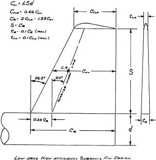
Figure 1 - Low-Drag, High-Efficiency Subsonic Fin Design
Fin Shape: Which is a better fin planform? Delta, rectangular, tapered-swept,
clipped delta ... or does it really make any difference? I believe that it does.
When a model rocket flies at zero angle of attack, its fins with symmetrical
airfoils produce no lift force. Therefore, the only fin associated drag is the interference
generated at the junction of the fin root and the cylindrical body and the friction
caused by the boundary layer of the airflow over the fin surfaces. Theoretically,
the interference drag caused by the fin-body joint can be reduced by using a triform
fin configuration instead of cruciform, and by fillets at the fin-body joint; this
drag can never be eliminated, but it can be reduced. Because of the small fin chord,
airflow over their surfaces is probably laminar at all model rocket flight speeds.
A good finish is important to minimize friction drag.
However, no model rocket flies continually at zero angle of attack. Disturbances
tend to swing it away from zero to some angle of attack. When this happens, a fin
assumes an angle of attack to the airflow also and therefore begins to generate
lift. This swings the model back to zero angle of attack so that it flies straight.
So, a fin must be treated as a small wing with a symmetrical airfoil, and we must
begin to take into consideration such wing factors as aspect ratio, slope of the
lifting coefficient as a function of angle of attack, induced drag (drag due to
lift), stall, tip vortices, etc.
This introduces so many variables that a model rocket designer must resort to
"trade-off's" or compromises. The trade-offs a designer makes become like a signature;
you can nearly always spot his designs. As an example, check a couple of manufacturer's
catalogs. One firm's models generally use a tapered-swept fin planform. Another
is partial to clipped-deltas with no trailing edge sweep. Yet another will favor
trapezoidal fins. Often, the fin planform is selected on the basis of aesthetics"
(a model rocket must look like a rocket before it sells well as a kit). There is
nothing wrong with the aesthetic approach; often it results in very high performance.
There is much to be said in favor of the airplane designer's truism: "If it looks
right, it will fly right."
However, we've got a miniature wing hanging out there called a fin. Scientific
principles that apply to wing design hold true for model rocket fins. Different
wing planforms have different purposes. The same holds true for model rocket fins.
A fin planform should be selected as a result of a trade-off analysis based on the
end-use of the model rocket.
Let me add here that I have no criticism, implied or intended, relating to any
designer or manufacturer or the models designed and sold. I am trying to let you
in on some of my design philosophy, that's all.
I would use a tapered-swept planform on a model only if it were absolutely necessary
to move the CP further aft, and if there were no other way to accomplish a CP shift
than by sweepback. A sweptback planform - sweptback leading and trailing edges -
is a transonic-supersonic planform. It has serious drawbacks when used on a sub-sonic
model rocket. Induced drag due to sweepback is higher than with a non-swept planform.
In addition, the tips of a sweptback planform stall before the root. If your model
gets into some high angle of attack swings, the farthest aft portion of the fin
- that you need the most - becomes ineffective first. Tips stall, the drag goes
up and the lift decreases.
If you have a short, squatty altitude model likely to undergo wide excursions
of angle of attack, or if you want your model to remain stable over wide angles
of attack, or if you have a heavy model likely to get into high angle of attack
regions because of inertia - the delta planform would be suggested. Lift curve slope
on a delta planform is not very great, but it will perform out to 45° angle
of attack or more before it stalls. There is much to recommend a delta planform
for model rockets. It is an excellent compromise with good lifting qualities and
good drag qualities as well, in addition to its ability to operate over a wide range
of angle of attack without stalling, its structural stiffness, its abundant gluing
area at the fin root and its freedom from warping or fluttering.
But if you want the lowest possible induced drag, the clipped delta with carefully-formed
tips is the answer. I have carried out a great deal of research into several aerodynamics
texts and looked at a lot of data from various wind tunnel studies. The result is
the clipped-delta planform used on the Morlin-I. Design parameters of this clipped-delta
are dependent upon the diameter of body tube used, and these are spelled out in
Fig. 1. The 20° sweep of the quarter-chord line does not increase the induced
drag appreciably because this varies as a cosine function or quite near to it. The
taper ratio (ratio between the tip chord and root chord) is 0.5, which closely approximates
the proper, spanwise, aerodynamic loading characteristics of the classical, low-drag
elliptical planform (Spitfire style). If a well-streamlined symmetrical airfoil
is used on the fin, pressure drag will be nearly zero, even for a fin thickness
10% of the chord. The tip shape as shown is very important. This shape is the major
controlling factor over size and strength of the tip vortex, and this contributes
mightily to induced drag. This fin planform should stall at about 10° to 20°
angle of attack, but it has mighty powerful lift which acts as restoring force.
Having triggered what I hope will be some controversy on fin design, I invite
you to comment.
Surface Finish: Surface finish is the most overlooked, neglected and misunderstood
area of model rocketry. The science of aerodynamics plainly states that our models
fly smack in the middle of the "transition range" of Reynolds Numbers. At low Reynolds
Numbers (at low speeds or with small dimensioned models), the boundary layer is
laminar. At higher Reynolds Numbers, it is usually turbulent. The friction drag
coefficient for turbulent boundary layer cases is often twice or more that of the
laminar boundary layer. It behooves a model rocket builder, wanting to reduce drag,
to try to maintain a laminar boundary layer over his model. A laminar boundary layer
can be "tripped" into a turbulent boundary layer by a projection into the boundary
layer as thin as 0.0003". A sloppy nose-body joint can trip it easily, and the friction
drag on your model is thereby doubled at least. A rough paint job can trip it. Undoubtedly,
the launch lug trips the boundary layer on one side. This seems to indicate that
a model rocket should have a glassy finish with no protuberances.
Eliminate the launch lug by using a tower launch. Use no decorative tape rings
or even decals. Eliminate the nose-body joint by using some manner of rearward-ejecting
recovery device (this is difficult and may add enough weight to offset any drag
reduction produced by eliminating the joint).
Of course, this means that the first time you ding the model in any way - goodbye
reduced drag! But you can gain significant performance improvement by filling, sanding,
painting, compounding, rubbing, waxing, and polishing your altitude model.
In the future, we'll explore the fascinating "whys" of some of these points.
Posted February 5, 2024
(updated from original
post on 4/1/2017)
|