|
Modern day scale models are
amazingly detailed with functional miniature instruments, control yokes and joysticks
moving in unison with stabilizer, rudder, ailerons, throttle, and others. Access
to relatively inexpensive 3-D printing, laser printers, and laser cutters has greatly
enabled scale modelers. The state of the art has advanced for far that competition
is extremely stiff. Even so, in the 1960's when this "Cockpit Details for the Scale
Model" article appeared in Air Trails magazine, the skill level was quite impressive
given the resources available at the time. This particular subject is an instrument
panel for a Piper J3 Cub, but photos from scale contents of the era showed highly
detailed cockpits for civilian and military aircraft ranging from Cessna 180's to
B-36 bombers and F−86 Saber jet fighters.
See also Instruments
for the Scale Model, from the same issue.
Cockpit Details for the Scale Model
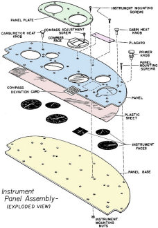
Piper J3 Cub Instrument Panel Assembly (exploded view)
Text and Art by Jim Triggs
For many years we have seen quite an assortment of large R/C planes and flying
scale jobs, most of them gleaming with a fine finish, the product of many hours
of the model-builder's loving patience and painstaking craftsmanship. In almost
every case a closer look at even the best of these models reveals a cockpit woefully
devoid of any detail whatever while others display only the crudest attempt at detailing
the interior of the airplane.
In the case of the average modeler, it is an almost complete lack of information
or data concerning airplane interiors, cockpits, instruments, which prevents him
from including them in a scale model. Other model-makers who may be thoroughly familiar
with the more conventional methods and techniques in putting together a model airplane,
find themselves at a loss to cope with the construction of the many instruments,
dials, knobs, switches, controls, and other gear found in the cabin or cockpit of
even the simplest airplane.
It would seem a shame to lavish hours of hard work on a big R/C or scale plane
that has no discernable inside detail which takes only a small portion of the total
time necessary to build such a model but which makes the ship a real outstanding
job. While it is true that some of the scale radio designs allow little room in
the cabin for excessive detailing, it is still possible to include some in most
cases.
First consideration in building an accurate representation of cabin or cockpit
detail into a scale model is accurate information. While this data is found in many
places, the best source is publications which often publish photos or details of
cockpit arrangements of various aircraft, both military and civil. Such a photograph
will at least give the modeler a partial picture of cockpit detail and panel layout.
The trick is to accumulate enough data to get the whole story.

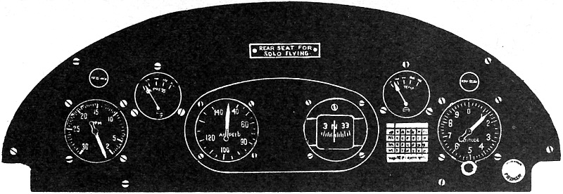
Piper J3 Cub Instrument Panel.
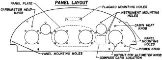
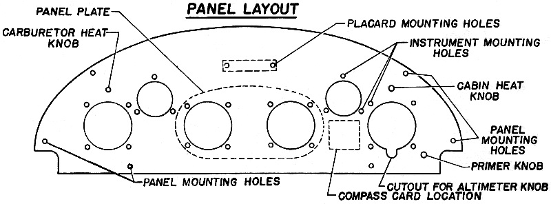
Piper J3 Cub Instrument Panel Layout
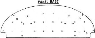
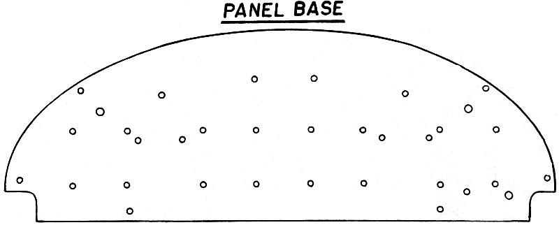
Piper J3 Cub Instrument Panel Base
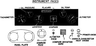
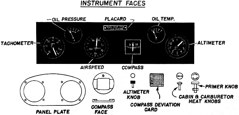
Piper J3 Cub Instrument Faces
Further research may lead the modeler to write to the various aircraft manufacturers
for data. While manufacturers of military airplanes may be hesitant about providing
such information due to security or business considerations, other concerns may
be very happy to provide assistance through their public-relations or advertising
departments. Very fine brochures and catalogs of the private plane manufacturers
are readily available. Most of this literature provides very good information and
photos of the airplane concerned, inside and out. Piper Aircraft Company, for instance,
publishes full color booklets on their Tri-Pacer and Super Cub models which provide
all the information necessary to make a completely detailed interior of either airplane.
Some model-builders have placed their reliance on some of the meager information
provided with the average kit. Far too infrequently will the commercial kit give
any accurate cockpit detail.
In his research, the modeler will soon become familiar with cockpit and instrument
arrangements of various airplanes. It becomes apparent that certain arrangements
are typical regardless of the type of airplane. Note the separate grouping of flight
and engine instruments on the panel. The arrangement technique will often help out
the modeler who is unable to determine the exact position of a turn and bank indicator,
or oil pressure gauge from his data.
In finishing a scale model interior, close. attention to detail and neat workmanship
is essential to a convincing finished product. One of the points most frequently
passed over or ignored in the scale cockpit is the structure of the interior walls
and floor of the cockpit. Most private and commercial airplanes are finished inside
- that is, the bare structure of the airframe itself is covered with upholstery,
headlining, and/or some other material, plastic, leather, etc. In the case of the
military airplane of older vintage, the bare bulkheads, channels, and stringers
of the airframe are usually exposed and visible in the cockpit with the only protection
to the pilot afforded by the outside metal skin or fabric covering of the airplane
itself. On more modern military aircraft, interior structure may vary in construction
detail but are seldom finished or upholstered as is the case with civil planes.
For the model-maker, it is just as important to include this detail as it is to
model the instruments or controls accurately. A little imagination and ingenuity
will provide the materials and techniques to accomplish this phase of the model.
For instance, it will be found that various flock-covered papers, in many colors
will often simulate exactly the types of upholstery used in many private and commercial
airplanes today.
Perhaps more interesting than upholstery will be other inside gear and equipment
contained in the cockpit. The control stick, wheel, rudder and brake pedals, flap
handle, control linkage system (or that part of it which may be visible), throttles,
knobs, switches and radio equipment can be modeled from easily obtained materials
with some ingenuity. While many of these tiny and often intricate items can be built
up in brass or other metals and delicately soldered, there is no reason why they
cannot be made from scrap balsa, heavy paper, or other more easily worked materials
and painted appropriately.
In finishing his cockpit, the modeler should not overlook some of the small details
such as a compass, deviation card, operational placards, safety belts, etc. While
some of these little cards and placards may be so small, especially in any scale
under 2", that any attempt at making legible lettering would be foolish, indication
of such lettering is desirable. A line of tiny dots; spaced as words might be, uniform
and even, will almost convince the viewer that he is seeing lettering, even if it
is too small to read.
Probably the greatest stumbling-block is the instrument panel itself. Assuming
that you have spent some time in research and have adequate pictures and data on
the panel, how do you proceed?
The accompanying drawings show the layout and steps in putting together a really
detailed panel for the Piper J3 Cub. In exact 2" scale, this should fit any Piper
Cub model in this scale with possible small variations in the extreme width or height
of the panel due to the structure of the fuselage. In the older Cubs, the top quarter
of the panel is curved toward the front of the airplane slightly; this curve could
be put into the panel after it was assembled and finished.
First layout the panel, panel base, and panel plate. These parts can be made
of thin balsa or even heavy paper in scales up to 1 1/2". In any scale larger than
2" it would be wise to use thin sheet aluminum or brass for the panel to avoid distortion
or warping. Cut these parts out together so that their edges coincide exactly. Layout
all of the holes in the panel, panel base, and plate. Drill the instrument mounting
holes and holes for knobs with a No. 56 drill (a little less than 1/16"). The holes
for panel mounting screws can be made a little larger, about 1/16", to accommodate
small round head wood screws which can be used to mount the panel to the fuselage
structure later. Clamp the panel, panel base, and plate together, then drill all
three parts at the same time so that all of the holes will be aligned. Layout the
instrument cutout holes carefully and cut them out of the panel. If your panel is
wood, keep the holes perfectly round and with sharp edges. If your panel is aluminum
or brass the holes can be cut out roughly and filed carefully to a perfect round.
Paint the panel and panel plate flat black after all holes are drilled and cutouts
smoothly finished.
Cut the instrument faces out and cement them to the panel base; be sure they
are properly centered under the instrument cutout holes in the panel. The placard
may be cemented to the panel in the proper position and holes punched through for
the mounting screws. The compass deviation card is paper and is likewise cemented
to the panel in the indicated position at the right of the magnetic compass.
A sheet of clear plastic to simulate the glass plates covering the instruments
is sandwiched between the panel base with instrument faces and the panel proper
as shown in the exploded drawing. With these parts held in alignment, the mounting
holes can be punched through the plastic sheet with any sharp tool such as a scriber.
The panel, panel plate, plastic sheet, and panel base are assembled, using short
00-90 machine screws (round headed) through the front of the panel; 00-90 hex nuts
are tightened on the ends of the screws in back of the panel base. These tiny machine
screws can be either brass or steel. If brass, they should be painted flat black,
as is the panel. Steel screws may be left shiny. Screws in these tiny sizes are
available in most hobby shops, as are the small drills described.
The compass face can be built up from thin balsa and a small screw set in to
represent the adjustment screw. Paint this part flat black and cement it into position
in the compass cutout in the panel. Compass face should protrude slightly from the
panel.
Carburetor heat and cabin heat knobs can be made up with short pieces of hardwood
dowel with the large rounded heads made from soft balsa. The shafts of these knobs
should be painted aluminum with the heads painted shiny black. Make an indication
of lettering across the face of the knob. The knobs are glued into the appropriate
holes above the altimeter and tachometer dials.
Altimeter knob is made up as above except that its head is smaller and flat across
its face. Although this knob is knurled in the prototype, this would be all but
invisible in any scale smaller than 2 1/2" or 3". Paint this knob flat black and
glue into position in its hole below the altimeter dial. The head of the knob should
protrude above the face of the panel in the cutout provided.
Primer knob is made up in wood or metal and painted aluminum. The stamped lettering
of the original can be duplicated or at least suggested pretty well with the sharp
point of a fairly hard pencil. Slip a small hex nut on the shaft of this knob and
cement the shaft into its hole on the panel to the right of the altimeter. The nut
on the shaft should be flush against the surface of the panel.
In inserting these knobs into the panel assembly, the 00-90 holes originally
drilled for them may be enlarged to suit the exact diameter of the shafts by using
a small triangular reamer such as is sold in most hobby shops for model railroaders.
Posted September 17, 2022
|