|
An unsigned e-mail arrived requesting
that I scan and post this construction article for Harold deBolt's Crusader from the
August 1959 edition of American Modeler. I offer the service free of charge
for anyone that writes, provided I already have the magazine. There have even been a
couple cases where I bought editions on eBay after people asked for them in order to
be able to post the articles. I'll never understand people who don't have the courtesy
of signing an e-mail when asking for a favor (this isn't the first time)... and no excuses
about being old and not knowing how to use the computer - would you do the same thing
with hand-written letters? Then again, maybe he hit the Send button accidently before
finishing.
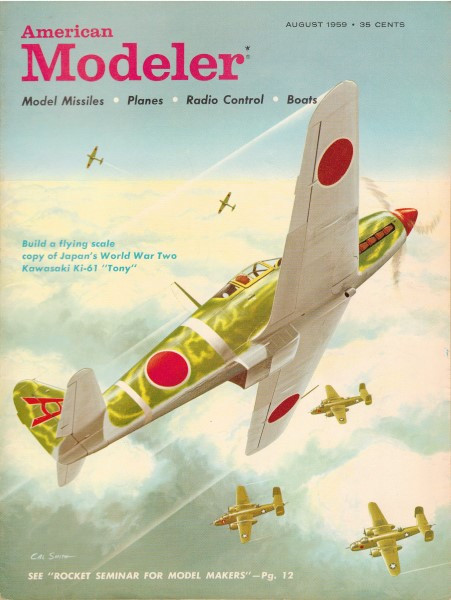
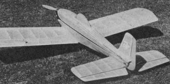
Harold deBolt's Low-wing Crusader for R/C
Here are all the "whys" and "hows" of low-wing flying. DeBolt gives the low down (pun).
on what's best; read this informative report!
 In presenting the "Crusader" I would like to
do so in more of an informative way rather than as a strictly constructive article. Space
is limited and there is so much that can be gotten from this model that it seems foolish
to linger overly long on construction when so few that may be building one will actually
need such information. In presenting the "Crusader" I would like to
do so in more of an informative way rather than as a strictly constructive article. Space
is limited and there is so much that can be gotten from this model that it seems foolish
to linger overly long on construction when so few that may be building one will actually
need such information.
Some 4 years ago George Swank and I decided that the time was right when we could
come close to duplicating control line stunt maneuvers with R/C models. We embarked upon
an extensive evaluation project which took us through most every sort of model configuration.
To make a long story short we found that the low wing design seemed to offer the best
possibilities for top inverted performance. The reasoning being that when a low wing
is inverted it is in effect a "high wing" and except for the dihedral effect it should
have the highly desirable stability inherent with a high wing. The results found
at that time indicated that it would be imperative to use a low wing IF we were to fly
inverted equally as well as upright. The project was shelved at that point simply because
it became increasing important to spend more of the available time trying to solve the
intricacies (at that time) of the then new multi-control systems. Also, the advantage
would have been relatively small since the rules then would not have credited us for
our inverted flying.
About
a year ago an old friend of ours, Fred Dunn, startled the R/C world with reports of the
fabulous performance from his low wing design. These reports ignited the old spark and
I decided to have another look at the low wing using a more modem approach.
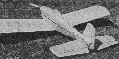
A lot of consideration was put into this first design and the "Crusader" was built
as a strictly experimental model to evaluate these design features and to provide an
opportunity to tryout some ideas for use with low wing types which seemed to have merit.
Now the project has been completed and I am pleased to say that it can be considered
to be very successful, hence I feel that many others can get some good from these results.
In general the basic aim of the "Crusader" design was to obtain the ultimate in inverted
flying ability and still have a model which could be flown without excessive difficulty.
It was felt that the model should be able to perform all upright maneuvers while inverted
if the aim was to be achieved. To this end all factors were directed towards a maximum
of inverted performance and when a compromise had to be struck it was allowed to lean
towards the inverted factor.
When you think of inverted flying the first thing which comes to mind is the airfoil;
you must of course have one which is efficient in both respects. To me there can not
be any other choice for this other than a full symmetrical, after all if it is to have
equal action in both directions it must be identical on both sides. For the past several
years I have been using a well proven and extremely stable symmetrical foil, as a result
there was no problem in choosing the foil to be used on the "Crusader"- it would be this
one.
The force setup (angular settings of the wing and stabilizer relative to the line
of thrust) used is a bit unusual for a symmetrical type airfoil, however there was a
good reason for it. One of the problems with a low wing when inverted is that the tail
tends to fly high and thus the effective center of lateral area is high also. This sets
up a unstable factor which tends to cause the model to drop off on one wing or another.
It would not make too much difference which way the fall-off would occur.
 While flying my Live Wires I had noticed that
they had extreme stability in this respect while flying inverted. Once on their back
they would stay there with no tendency to fall off; a flat bottom airfoil was in use,
of course. In analyzing this feature I finally realized that the full down elevator which
was required to hold them inverted was also forcing the tail end of the airplane to fly
"low". Thus, in effect this attitude was creating a low center of lateral area while
inverted giving the added stability which the Live Wire seemed to have. While flying my Live Wires I had noticed that
they had extreme stability in this respect while flying inverted. Once on their back
they would stay there with no tendency to fall off; a flat bottom airfoil was in use,
of course. In analyzing this feature I finally realized that the full down elevator which
was required to hold them inverted was also forcing the tail end of the airplane to fly
"low". Thus, in effect this attitude was creating a low center of lateral area while
inverted giving the added stability which the Live Wire seemed to have.
I felt that it would be extremely desirable if something of this nature could be worked
into the low wing design. It could not be duplicated exactly for if it was the symmetrical
foil would be lifting when the inverted flat bottom type was not, resulting in an inverted
climb instead of tail low level flight.
The symmetrical airfoil lifts well at angles as low as 1 to 2 degrees and with this
knowledge in mind the wing was set at a 5 degree positive angle of incidence. The stabilizer
was set at a 4 degree positive angle although this is not the least bit critical as tests
indicated anything from 3 to 5 would do the job. With these angles upright flight is
minus any ballooning tendencies due to the careful balance of stabilizer lift relative
to wing lift, much as in the Live Wires.
However, when inverted enough down pressure must be exerted by the elevators 60 that
the wing will be forced to at least a 1 degree angle of attack before level inverted
flight can be obtained. In doing this the elevator action also forced the tail end of
the model down somewhat in the same manner as with the Live Wire. Thus, the lowest possible
center of lateral area inverted was obtained consistent with the rest of the model's
design. In practice this seemed to be one of the more creditable assets which the model
had, it did fly inverted with the least tendency to fall off that we had ever observed
in an inverted type model.
One of the first questions which I was asked at a flying field was "How much thrust
offset do you have in the 'Cru-sader?'" My usual reply was "none at all" accompanied
by a silly grin. Almost every time the result was disbelief as the questioner walked
away. This zero thrust was one of the things which I am most proud of simply because
I tried hard to achieve it and feel that it is most necessary for the ultimate in all
around performance.
My reasoning was brought home hard to me one night during a "bull session" in Ernie
Kratzet's cellar. In discussing inverted flying he stated that side thrust had an opposite
effect from what it had upright while in the inverted position, yet the torque which
sidethrust was used to compensate was the same. In other words you could expect torque
effect and side thrust to team up when inverted. We had some dramatic demonstrations
of hanger flying with one of Ernie's models that night; in the end I had to admit that
he was right! Since then I have used every effort possible to get rid of all thrust offsets
on models intended for inverted flight.
The "Crusader" has no down thrust because of the high thrust line relative to the
center of resistance plus the effect obtained from the lifting stabilizer in its Live
Wire force setup. The side thrust was eliminated by creating a careful aerodynamic balance
of forces pivoting about the C.G. By creating a careful balance here the torque effect
was balanced out by all the other factors which could be worked against it. The end result
is an arrangement whereby the thrust remains the same no matter in what position the
model is flying in.
Another advantage obtained from this neutral thrust comes in ground handling. At taxi
speeds torque is much more effective than any counteraction used against it. The natural
result is that the model tends to follow the torque at low speeds, side thrust being
ineffective the model will tend to turn with the torque and must be compensated for.
With no side thrust needed this model tends to go straight under slow speed taxiing conditions.
I have little doubt but what the "Crusader" could be flown with the simplest form
of controls, however it would seem to be a waste of good potential to try that. In any
case the "Crusader" was flown with the reliable Bramco "Regent 8" for the radio and Model
MC type Multi-Servos for the actuators. With this equipment rudder, aileron, elevator,
engine, tail wheels and wheel brake controls were used ... a "full house."
The rudder was used as a basic control at first. The ailerons were used only for maneuvering.
Both of these controls used the MCR type servo for its full self-neutralizing features.
The elevator and engine used the MCE type servo. For the MCE engine actuator the two
normally-closed relay contacts which usually actuate the neutral circuit were not connected
(two wires were omitted) so that with this arrangement the engine servo was completely
trimmable giving infinite engine speed control.
The MCE used on the elevator was used as intended, self-neutralizing and yet trimmable
about neutral. This trim at neutral allowed the use of the "down-trim" necessary to fly
the model inverted with "hands off" on the elevator. The other controls were picked off
these in the usual manner now prevailing.
 After flying the model for some time trouble
was encountered during takeoffs (just after being airborne) and during the last stages
of landing approaches a wing would drop and the rudder control just would not lift the
wing quickly enough under these circumstances. It was found that a tendency to slow the
model down so a short field landing could be made was causing me to fly it too slowly
and actually stall out. The simple answer was to switch to ailerons as the basic control
so that the low dragging wing could be lifted quickly when needed. After flying the model for some time trouble
was encountered during takeoffs (just after being airborne) and during the last stages
of landing approaches a wing would drop and the rudder control just would not lift the
wing quickly enough under these circumstances. It was found that a tendency to slow the
model down so a short field landing could be made was causing me to fly it too slowly
and actually stall out. The simple answer was to switch to ailerons as the basic control
so that the low dragging wing could be lifted quickly when needed.
Another answer would have been to adjust the elevator servo so that no "up trim" could
get into the elevator, thus the model would always have the flying speed it needed. I
think other flyers will encounter my trouble when switching from a high wing or bipe
to a low wing. I tended to use a nose-up attitude with the model to slow it down on approaches
which is okay with the stability inherent in most models - however with low wings this
is N.G. and you must fly them in all the way. The catch is to break yourself of this
habit before it creates trouble or else use ailerons only for directional control.
Some of the features used on the "Crusader" proved to have a lot of merit. Common
dural gear saved weight and the work involved of a wire type gear in the wing. Just install
the usual hardwood mounting block in the center section of the wing. The dowels are buried
in the wing which makes a neater job. The only word of advice necessary: strap the rubber
bands on tightly, otherwise the gear could dig into the wing skin should it jump off
of its block.
The "Crusader" uses the standard removable R/C unit as in my other models. It is inserted
through the wing opening eliminating access hatches. If you are familiar with this box
you will remember that the engine servo has been on the right hand side. With the addition
of the aileron servo it has been necessary to move the engine servo to the opposite side
and install the aileron servo on the right. By doing this the servos need no alteration
and can be used in the stock manner.
The aileron system on the "Crusader" was an experiment to give something more simple
to install and maintain. The hinge arrangement which has worked very well was a "steal"
from one which I have long used in control line. There is nothing simpler than the trap
and dowel hinge but be sure to use material for the strap as called for. Too light a
metal tends to fatigue after long usage.
This model used a torque rod type of control linkage. As mentioned before the the
servo for it was mounted in the R/C box. This was done to remove the weight from the
wing and to make the box interchangeable between models which does cut the expense of
owning more than one model. Removing the weight from the wing can help save it a bit
if a "clobber" should occur. The torque rods were 1/16" music wire bent 90 degrees at
the ends (one rod for each aileron). Suitable fittings were made to connect the ailerons
and servo push rod to them.
This system proved to be "soft" in action and possibly could have suffered from "blow-back"
in the air, otherwise it was simple and light to install. The answer I found in one of
my Bipes which also used it. I simply arranged the leverage so that the aileron reached
its limit stop before the servo reached maximum travel. What happened was that the servo
tended to "wind up" the torque rod after the aileron had reached full movement and thus
you had a "solid" aileron action in the full control position. Frankly this worked out
quite well and no trouble was encountered, however, I felt that the "softness" was a
weak point.
The system shown on the plans is brand new and I call it the "flexible push rod."
It was not used at all in the original "Crusader" but tests with it in other planes have
shown such good results that I felt it best to present it here. This arrangement is simplicity
itself. The heart of it is a piece of flexible braided cable (size .050) which runs in
a piece of suitably bent aluminum tubing to get around the corner to the aileron's horn.
It is a "positive" system with absolutely no softness and no "play" providing the 3 holes
required in the various horns are held within tolerance. I feel that it has a great future
and is just about as simple as anything can be. For those liking a wing-mounted servo
it is a simple matter to install the servo where the bell crank is shown and operate
the push rod directly from the servo.
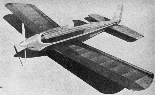
The results of all these ideas have proven acceptable on the flying field. The model
itself proved out well by weighing in on a par with other types; at 5 1/2 lbs it is considerably
lighter than most other low wings. This lighter wing loading paid off in better maneuvers
and the ability to perform well with an average .35 engine.
After the author got over the "shock" of switching from high wings to the low wing
some really good flying was obtained. I do think however that one should have some multi
experience before attempting to fly any low wing. You must fly these airplanes all the
time and without experience with elevators that can be a bit rugged.
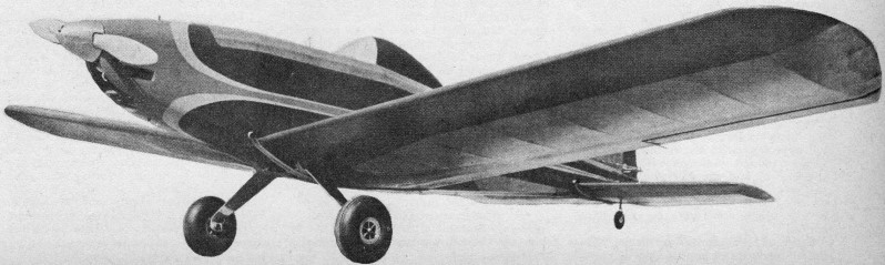
The "Crusader" is a very clean flying airplane, has no bad tendencies and responds
instantly to all controls. Both inside and outside loops are smooth and equal, rolls
are on a "string" so to speak and very little elevator action is necessary to keep them
that way. Upright flight sufferers for smoothness when ailerons are used for directional
control but this is solved by using rudder for turns while at altitude. Inverted flight
is pretty nice, once there long periods of time go by without need for correction and
then a slight application of aileron is enough. All upright maneuvers are easily accomplished
while inverted simply by remembering as we had to in control line that "up-is-down-and-down-is-up"
PLUS that "right-is-left-and-left-is-right" on the rudder!
Inverted flight can be entered from all three ways, half an inside or an outside plus
using a half roll. I found the half roll to be more desirable simply as practice for
doing the 2 pt roll. Once inverted you adjust for the type of flight desired by trimming
the elevator. A small amount of down trim will give level inverted climb and of course
full down brings it around to upright again!
Once you set the amount of trim desired the model is flown elevator "hands off," simultaneous
control is definitely not required. Directional control inverted by rudder is more sluggish
than upright so in general ailerons are used instead. They are just as effective as upright
plus the fact that they react in the same direction as upright, you don't have to reverse
your directional thinking by using them!
This being one of the first really fine inverted machines that the author had flown
much time was spent trying out new sorts of maneuvers which this perfected inverted flight
offered. We had a lot of fun learning how to do them and of course got our share of applause
for accomplishing them the first time.
Of these maneuvers one is Dick Branstner's favorite, an inverted tail spin. Rather
spectacular and confusing to watch it is relatively easy to accomplish. When inverted
you simply apply full-down elevator until the nose is straight up, then neutralize. When
speed has just about completely diminished you apply full-down and full-rudder simultaneously,
the result is a tail spin with the model upside down! Another crowd pleaser is to go
into a inverted "Cuban 8." This is the regular Cuban 8 entered from the inverted position.
It seems funny to see the model in the upright position at the middle of the 8 where
ordinarily it would be inverted. The fact that the "Crusader" is a tight-turning airplane
makes this one much more pleasing to watch than with some other models.
The show stopper proved to be an inverted "Victory Roll." This one is accomplished
from an inverted level flight position, usually near the end of the flight. From this
position you apply a bit of up trim (or take out some of the down) which puts the model
into a shallow inverted dive. When you have approached the ground about as close as safety
permits you apply full down elevator until the nose has come up to about a 45 deg angle
and then the elevator is neutralized. Just afterwards you apply full aileron and hold
for the number of rolls desired releasing the aileron so that you come out in an inverted
position. To recover you trim for level inverted flight as usual. The "topper" is to
repeat it going in the opposite direction and recover upright followed by an immediate
landing. Shades of the "Blue Angels" ... we'll catch up to them yet!
In general I feel that the "Crusader" proved out the theories which Swank and I envisioned
4 years ago and that this is only a start towards some mighty fine flying that is yet
to come. The answer to it all is of course the marvelous improvements which we have seen
in R/C equipment during the intervening years.
I would like to say that I don't believe any low wing model is the best for the beginner
in R/C or maybe even for the novice in Multi, but for the multi-flyer with any experience
this sort of thing can be it ... a really "spirited model" with the sky the only limit!
"Crusader" Specifications
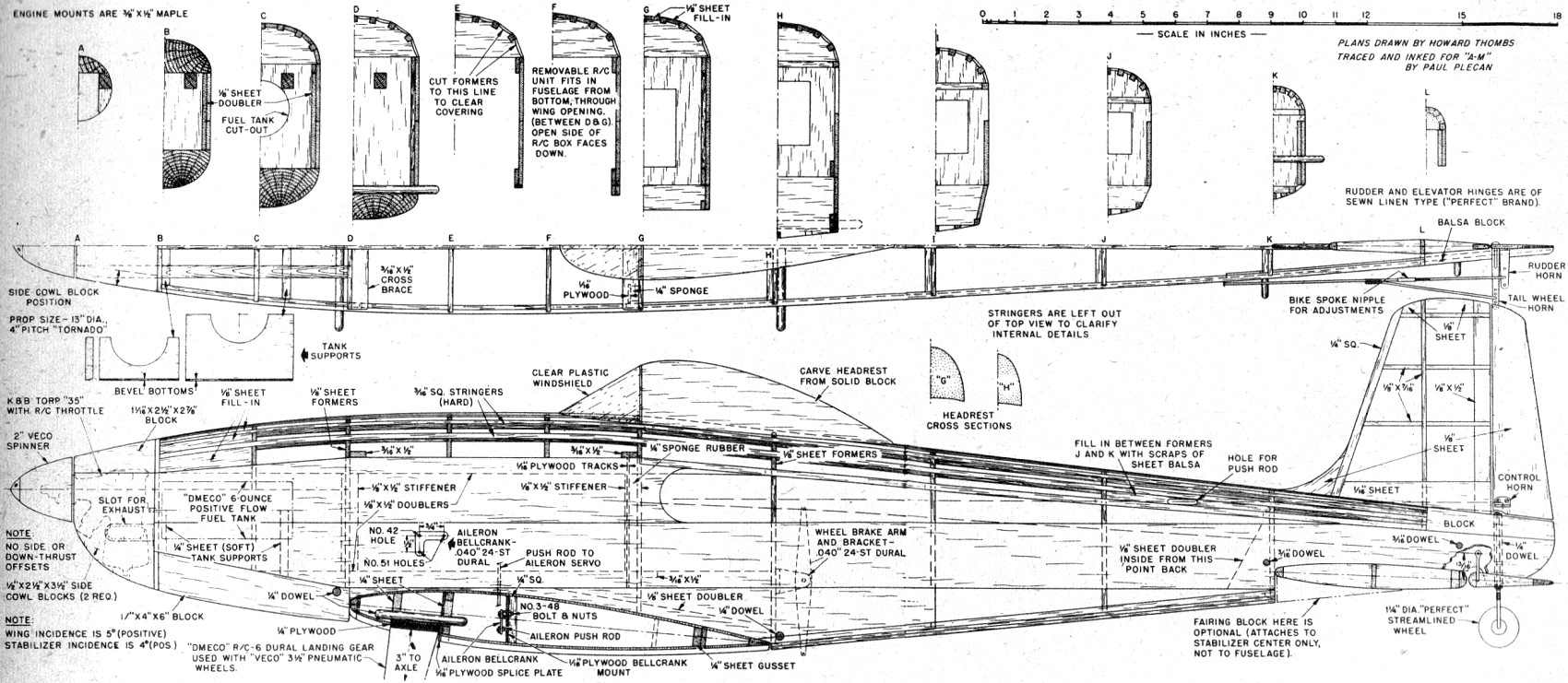
Wing Span, 66": Wing Chord, 13"; Wing Area, 858 sq. In.; Airfoil section, NACA 12%
full symmetrical; Wing loading, 14.6 oz./sq. ft.; Gross wt., 5 1/2 lbs; R/C equipment
weight, 28 oz: Power, K&B Torp R/C .35: Propeller, Tornado R/C 13-4; Fuel, K&B
Super Sonic 1000; Radio, Bramco "Regent 8"; Actuators, Model "MC" Multi-Servos; Fuel
tank, dmeco Model C6 oz Positive Flow; Wheels, Veco 3 1/2" R/C Pneumatic; Finish, Red,
trimmed with blue & yellow Aero Gloss.
 Harold deBolt's Crusader Plans
(sheet 1)
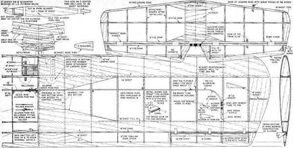 Harold deBolt's Crusader Plans
(sheet 2)
Full size plans for Crusader are on Group Plan # 859 from Hobby Helpers, 770 Hunts
Point Ave., New York 59, N.Y. (85c). Order by number rather than by name of model.
Notice:
The AMA Plans Service offers a
full-size version of many of the plans show here at a very reasonable cost. They
will scale the plans any size for you. It is always best to buy printed plans because
my scanner versions often have distortions that can cause parts to fit poorly. Purchasing
plans also help to support the operation of the
Academy of Model Aeronautics - the #1
advocate for model aviation throughout the world. If the AMA no longer has this
plan on file, I will be glad to send you my higher resolution version.
Try my Scale Calculator for
Model Airplane Plans.
Posted November 24, 2012
|