|
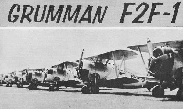
Here is an example of the Grumman
F2F-1, as presented in the September 1957 edition of American Modeler. Designed,
drawn and described by Paul Plecan. "The Grumman F2F was a single-engine, biplane
fighter aircraft with retractable undercarriage, serving as the standard fighter
for the United States Navy between 1936 and 1940. It was designed for both carrier-
and land-based operations." -
Wikipedia
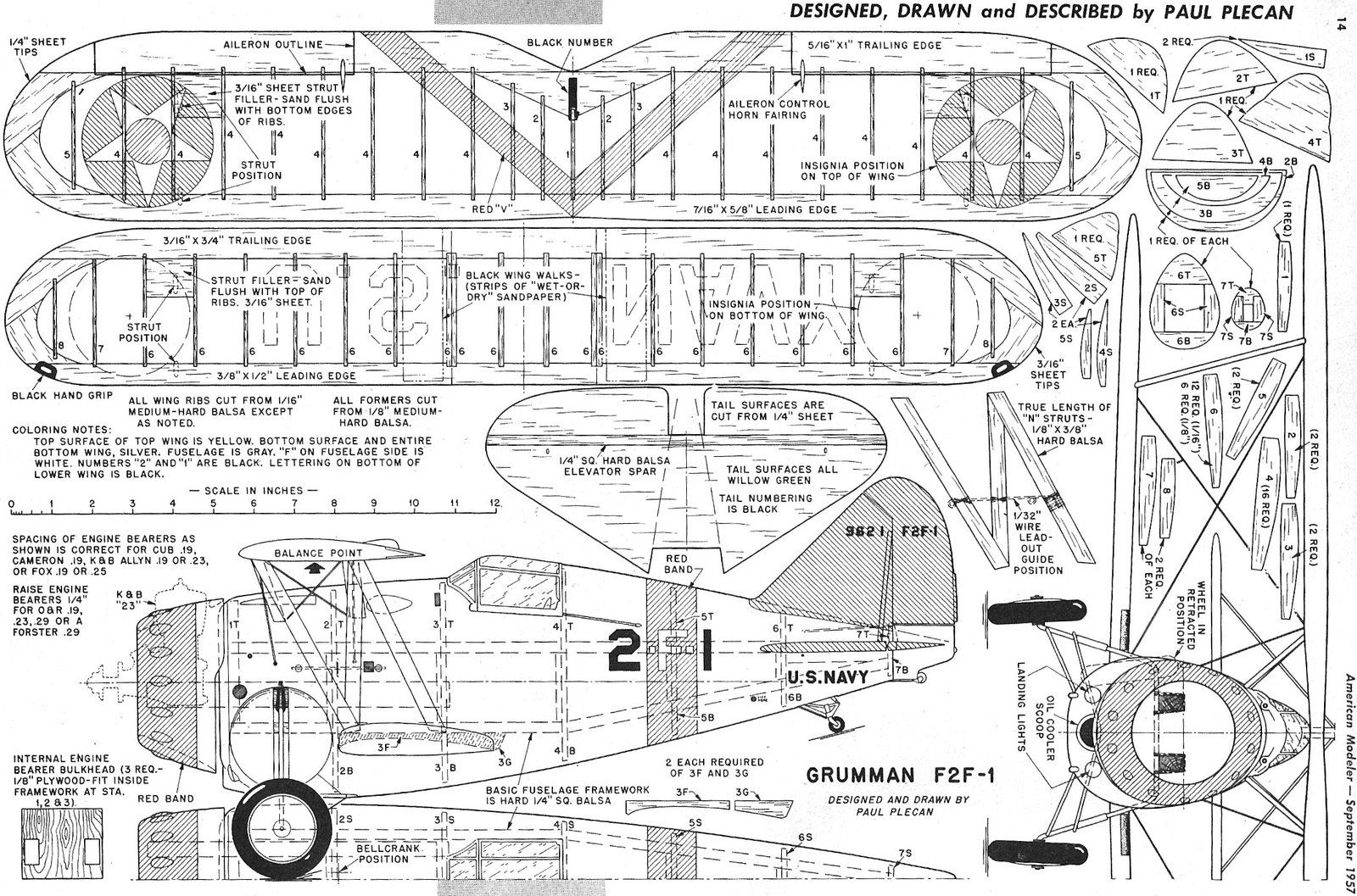
Click on the plans at the bottom for a larger version. You might be able to buy
full-size plans from the AMA plans
service. All copyrights (if any) are hereby acknowledged.
Grumman F2F-1
 Designed, drawn and described by Paul Plecan Designed, drawn and described by Paul Plecan
Of all fighter biplanes ever built, the early Grumman ships personify a pugnacity
and ruggedness apparent in no other type. Chunky, strong, the F2F-l was a fast fighter
for its time; one reason was its retractable landing gear. The F2F -1 was one of
the earliest fighters that had this feature in operational or squadron service.
First seen by the author at Floyd Bennett Field near New York in the mid-thirties,
the F2F-I was always considered a high priority subject for a U-control model. If
you like the F2F-l's looks too, let's build one ...
Easiest way to get going is to build the wings first. After cutting out the required
number of ribs and tip pieces, cut leading and trailing edges to size. Note that
ribs are notched into both leading and trailing edges. Once all the cutting is done,
cement together over the plan. The lower wing incorporates some dihedral, so crack
the leading and trailing edges (after cutting partly through) where the doubled
number 6 ribs occur. Propping up tips with scrap ⅜"
stock: under # 1 ribs produces the correct dihedral angle, so just let the cement
dry well while we tackle the fuselage.
A basic framework is built up of ¼" square balsa
longeron, followed by the various former segments as shown in the step-by-step sketches.
The suffix on each former part clarifies its position; T for top, S for side, and
B for bottom. Along about now it will be necessary to cut out 2 each of parts 3F
and 3G. Thickness is immaterial, but 3/16" or ¼" stock
would be fine. Former 3B is cut off flush with lower edge of 3F -3G so that top
surface of center section of lower wing" fits snugly against this assembly. Lower
wing should be covered and doped now so it can be assembled to the fuselage framework.
Silk is recommended "for maximum strength and resiliency. In assembling the lower
wing to fuselage, be careful to keep alignment right on the button when viewed from
above (they should be at right angles). The part remaining of 3B is now trimmed
an amount equal to thickness of wing at that point and cemented to bottom of wing.
We can now proceed with planking of fuselage. Use soft
⅛" x ⅜" balsa strips, starting near top longerons and
about parallel to them. Due to the pronounced taper of the fuselage from station
3 to the tail at 7, it will be necessary to taper the planking. This is easiest
if you have a really sharp miniature plane, but if not, a metal-edged rule laid
across edge of planking strip will guide your X-acto knife or razor blade for a
straight taper cut where you want it. Sanding wm achieve the slight bevel necessary
between adjacent strips; the finished fuselage should be practically devoid of slits
or gaps in the planking. More sanding is in order now to achieve a smooth surface.
Section forward of fanner 2B is carved from a block of balsa, 2¾" long by 1⅝" deep and 3¾" wide. If you so desire, the wheel-wells can be carved into
the sides of the block; however, many will choose merely to paint a 2½" circle in dark gray or black on the sides of the fuselage
in the same spot and let it go at that. For maximum strength, it is best to lace
the main landing gear strut to the inside structure as shown on plans. Strong sewing
thread or upholsterer's thread is fine for this, plus generosity with cement.
A plywood insert between engine bearers (or on top) is necessary for bellcrank
attachment. Laterally or vertically the position is not too important, but do not
change from longitudinal position shown; 1/32" aft of station 2 is ideal, as shown.
The line guide for the lead-outs on the "N" strut is positioned for bellcrank position
shown, so change it if you change the bellcrank position for any reason.
Tail surfaces are cut from ¼" sheet and sanded to
section shown in side view. Regular fabric hinges are used (or whatever type is
your favorite) and be sure ample movement of the elevators exists. If a small Veco
(2") bellcrank is used and the elevator horn is about the size shown, up and down
travel will be sufficient.
An important item of appearance will be the wheels. The narrow-tread tires and
wheels used on these older-type jobs make wheel procurement a problem. The right-type
wheels can be obtained. from Scalemaster Models, 28 Ionia, Grand Rapids, Mich. $1
per pair, postpaid. If you are making primarily a flying model, simplify the tail
wheel mounting into a single wire deal. Complicated stuff just doesn't hold up for
wear and tear of flying.
For those who may have trouble in getting top wing in place correctly on a biplane,
here is our advice. Cut a "jig" out of any thickness wood handy. This should have
the contour of the wing I undercamber for its top edge and the I shape of the fuselage
profile for its lower' edge (that portion of the fuselage directly under the wing).
Now if this jig is pinned or taped to fuselage and then wing taped to it, you will
have something to hold the wing in place while fitting the "N" struts. Brace the
top wing to the bottom with scrap strips and check alignment from above and from
front before fitting struts.
Brace wires are a definite help in (I will scan the rest of
the article on request)
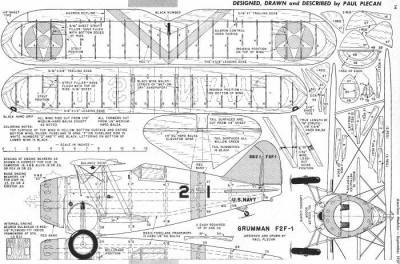
<click
for larger version>
Notice:
The AMA Plans Service offers a
full-size version of many of the plans show here at a very reasonable cost. They
will scale the plans any size for you. It is always best to buy printed plans because
my scanner versions often have distortions that can cause parts to fit poorly. Purchasing
plans also help to support the operation of the
Academy of Model Aeronautics - the #1
advocate for model aviation throughout the world. If the AMA no longer has this
plan on file, I will be glad to send you my higher resolution version.
Try my Scale Calculator for
Model Airplane Plans.
|