|
Website visitor Rob P. wrote to ask that I scan and post this
article and plans for Claude McCullough's "Chariot" radio control
model. The 58" wingspan high wing model features a pylon-mounted
.23-size engine. Although the original used rudder-only control,
no doubt Rob will use at least three channels, and maybe even add
ailerons for a fourth. He may even decide to adapt the Chariot to
electric power. Simple stick and sheet balsa construction helps
to make for easy, inexpensive building. Hopefully, Mr. P will
send a photo of his completed Chariot for posting here.
Mac's "Chariot"
By Claude McCullough
President & Contest Board Chairman. Academy of Model Aeronautics
(D.C.)
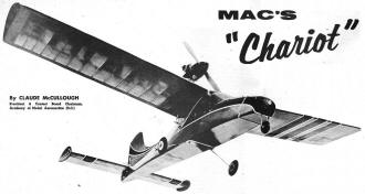
Just what the doctor ordered for the AMA's new
Pylon Racing Event, this remarkable radio plane is perfect for rudder-only
work
The original "Chariot" was built primarily as a sport flying
model for use at R/C picnic and evening fly-for-fun sessions and
the unusual layout was chosen mainly on the basis of its appeal
as an interesting, out-of-the-rut project. Considering this background,
I was agreeably surprised to find that the design has performance
features which alone make the high thrust line conformation something
for more radio control fans to sample.
Most valuable characteristic is the penetrating ability in a
high wind, something very necessary to successful rudder-only performance.
"Chariot" will stick her nose into a stiff breeze and make headway
when a more conventional job will not.
Next noticeable feature is maneuvering ability with smooth, on-the-track
turns without bouncy entry and pull-out. No design of equivalent
size that I have flown could handle power so well. The prototype
uses a .23 run full-out and I don't doubt that it could manage a
.29 if necessary.
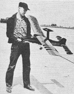
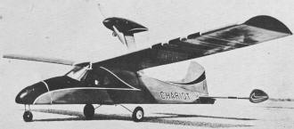
Claude McCullough and his "Chariot." Two-wheel
gear, replaced nose wheel; nacelle changed too
Needless to say, it is a rare day when a prop is broken. Not
that this can be considered a lesser advantage - as any R/C flier
who has to add a half a dozen broken props to a day's fuel and battery
bill can testify.
The prototype model was built from selected hard balsa, carries
copious battery and equipment choices, topped by multiple coats
of dope and at 20-oz-per-sq-ft wing loading can hardly be considered
acrobatic. Still it is evident that a plane built to a lower weight
with light equipment could more than hold its own competitively.
In particular the performance suggests itself as just the ticket
for the new AMA Pylon Racing Event.
Modelers who see the ship for the first time invariably marvel
at the pylon being able to stay in one piece, since on the original
version it is made from three laminations of 1/8" balsa. The secret
is the special rock hard grade from a stock Frank Zaic selected
for me some years ago.
At the annual Iowa R/C picnic I got to thinkering (as is my unfortunate
habit) with previously worked out adjustment and snapped stalled
the ship in under full power. The pylon, then fastened only at the
top and bottom of the cabin, was thrown completely clear of the
ship, but was not damaged at all. In repairs, 1/4" sheet wedges
filled-in to the bulkheads in front and to the rear (as shown on
the plan) were added and no further trouble has been encountered
despite my un-coordinated style of operation, which gives the ship
more than its share of hard knocks.
Because of the certainty that the quality of wood I had is not
commercially available now, plan shows a 1/8" plywood center with
ordinary 1/8" hard balsa outside. This provides a pylon of similar
weight and possibly greater strength with the addition of a more
positive motor anchorage point.
For the average version of the "Chariot" I would suggest a .19
motor. If you incline to heavy batteries and lots of dope, a .23
will be best. For lightweights with small radios a .15 cubic incher
may be fitted but I would not recommend anything smaller.
In construction I made use of one of Frank Zaic's neat aids to
modeldom, the 60" R/C Wing-Stab Kit. This ingenious shortcut comes
with die-cut ribs, shaped leading and trailing edges, etc.; besides
saving construction time is of the usual high quality wood that
has characterized FZ's productions. This item is sold only by mail
and is available from Model Aircraft Co., Box 333, Station D, New
York 3, N. Y. for $3.50 postpaid. If you wish to build your own
wing and stab from stock wood, full details appear on the plans.
In a ship of this type one consideration must be kept in mind.
To keep the C.G. in the proper spot, weight should be concentrated
in the nose and saved wherever possible in the tail. Don't spare
anything forward of the wing. Use the heaviest balsa and plenty
of cement. This has a practical as well as aerodynamic application.
The nose section takes bumps and thumps of ordinary flying that
in a conventional design are mainly absorbed by the motor-firewall
unit, and the extra strength is as necessary as the weight. To the
rear select lightweight wood and go easy on cementing, this section
is not subject to very much strain and will not require additional
strength.
My version used the McNabb 465-mc CR receiver - nice deal for sport
flying because you can get many more flights logged by using the
less crowded band and with little chance of interference. Proportional
pulse is standard as far as I am concerned for rudder only flying
and the results of the "Nats" R/C events give plenty of support
for that preference.
If you prefer another type of control there is ample space for
mounting available in the actuator compartment. Cabin and nose battery
box are both of dimensions that easily accommodate any standard
single channel unit and most small multi-channel outfits. Because
the choice of mounting is so dependent on the receiver and personal
prejudice of the individual constructor, I have not specified any
particular receiver installation-you can easily adapt your favorite
setup.
Fuselage is basically built upon the bottom crutch of 1/4" sq.
balsa, but instead of the usual method of building the crutch first
and then assembling the rest of the body on it, I believe it best
in this case to build two sides over the fuselage side view composed
of just the bottom longeron and the square forward cabin section
- the part on either side of the cabin window. After these have
thoroughly dried, the crutch bottom is completed over the fuselage
top view. Cabin top is completed with 1/4" sq. cross pieces.
Add Formers F-1 through F-9 to the crutch, using a right triangle
to align them correctly. Next step is to plank the bottom of the
crutch with 1/16" sheet balsa - 1/16" plywood being used under the
nose section, as well as in the area where the rear landing gear
is mounted.
Prepare the pylon for assembly by bolting the 1/32" brass motor
mounting brackets to the 1/8" plywood center. The crankcase nuts,
or radial mount adapter nuts if your motor has this type of provision
for radial mounting, are soldered to these brackets so that the
motor may be removed easily at any time. Cement the 1/8" hard balsa
sheet outside pieces on under pressure until very dry. Use hot fuel,
proof cement for this application as well as any other near the
motor nacelle or pylon.
Cement pylon to the fuselage bottom and secure in place at the
top by assembly of the platform pieces P-1, P-2 and P-3. Add the
1/4" sheet fill-in wedges to brace the pylon to F-5 and F-6. Fill
in around the base of the pylon with 1/4" sheet.
Motor nacelle is completed by install-ing 1/8" plywood firewall
and the balsa block cowl and nacelle sections. Top half is left
solid to add rigidity to the motor mounting, bottom half is hollowed
for installation of the fuel tank. This is of necessity rather odd
in shape, but is not difficult to make from brass shim stock.
Carrying the fuel in the nacelle is a recent change in the airplane.
Originally it used a Walker Pressure Tank in the nose compartment
feeding a regulator in the nacelle through several feet of fuel
tubing. Perhaps it was my application and operation of this device
but I got rather erratic results from this long distance pipe line
and switched to direct fuel feed which has given consistent motor
operation. The slightly different nacelle shape is better from an
appearance point of view than the original shape.
Fuselage is prepared for planking by shaping platform pieces
P-1, P-2 and P-3 with a knife to conform to the fuselage contours.
Run a sandpaper block along the crutch and shape it to blend in
smoothly with the change in fuselage shape. This requires an increasing
angle as you move toward the rear section.
Install all of your equipment mountings and make provisions for
control hookup to the rudder at this point. Plank the entire fuselage
with 1/16" sheet balsa and cement the 1/8" sheet fin in place. Leave
the cabin windshield and windows until after covering and decorating.
Compartment cover for the battery section in the nose is built
separately from 1/8" sheet section T-1 through T-7. It is held in
place by a rubber band in hooks in the fuselage side. Nose plywood
bulkhead "F" and the solid block nose are added finally and shaped
to the fuselage contours.
When the ship was first built a tricycle landing gear was used.
A characteristic of the high thrust line layout is a nose-down tendency,
one of the reasons for the good penetrating qualities. This resulted
in rather long takeoff runs however and it was not long before I
had switched to a two-wheel nose gear. There are cynics locally
who say this was another attack of an ailment to which I have at
times succumbed, known as "multiple-wheelitis." But if, you will
not buy a four wheel gear for your version on the basis of takeoff
tracking characteristics then consider the punishment that a short
single nose wheel must absorb. The two-wheel nose gear simply can
take it better.
I prefer the landing gear bolted in place with light aluminum
brackets instead of cemented so they may be easily moved or modified
if you are experimentally inclined.
If you elect to use a Wing-Stab kit there will be little time
needed for this portion of construction since these deals practically
fall together. Since the construction used is simple and straight
forward you will not have any trouble making up duplicates from
the magazine plans if you prefer to do so.
Note that several .different types of ribs are required - you
can modify your rib template accordingly as the proper number of
each are cut.
There are several minor changes from the standard wing-stab kit
that should be noted. The dihedral used was reduced from 3 1/2"
under each tip to 3". This amount has been quite adequate and gives
smoother turn recovery than higher angles.
The solid balsa stab tip of the kit has been replaced with an
endplate of 1/8" sheet balsa. A small fillet of scrap balsa block
is used to blend the cabin front into the wing.
Prototype was covered with red dyed silk and doped with clear
butyrate dope. Decorations are black with silver pin-striping, applied
with a ruling pen, ruler and french curves. Secret of successful
pin-striping with a ruling pen is keeping the pen clean by dipping
frequently in thinner, wipe and refill with fresh dope.
While it is often said that a design flew right off the board,
this can't be said of "Chariot." The first flights revealed what
I already knew by hand balancing - the C.G. was too far back. Moving
it forward by shifting batteries and actuator ahead quickly remedied
this. If you take care to mount everything as far forward as it
can be stowed you should be able to hit the point indicated on the
plans without any trouble. If you can't do it any other way, ballast
the nose block with lead - but this resort will be necessary only
if you have gone overboard building the tail and fuselage rear.
My original used no thrust offset. If any are required it would
be slight right thrust to counteract torque and upthrust if it is
desired to increase the climbing angle. Don't try to increase the
climb by changing the stab incidence unless of course the glide
also shows signs of being too shallow.
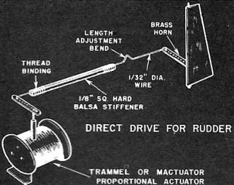
Direct drive for rudder
"Chariot" Bill of Materials
Four pieces 1/4" x 1/4" x 36" balsa fuselage longerons, cabin
frame; (1) 3/16" x 3" x 36 fuselage formers; (1) 1/8" x 2" x 36"
hard pylon outside; (2) 1/8 x 3" x 36" fin, stab endplates, nose
fill-in, compartment top; (5) 1/16" x 3" x 36" fuselage planking;
(1) 1/8" x 1/8" x 36" compartment top stringers; (1) 1/4," x 3"
x 36" platform pieces, fill-in; (1) 1/16" x 1/4" x 18" fuselage
backbone, 3" x 3" x 18" block nacelle, nose.
Following balsa if Wing-Stab kit is not used: (3) 5/16" x 1"
x 36" wing, stab trailing edge stock; (2) 5/8" x 5/8" x 36" wing
leading edge; (5) 1/16" x 3" x 36" wing planking; (1) 7/16" x 1/2"
x 36" stab leading edge; (2) 1/8" x 1/4" x 36" stab spars; (5) 1/4"
x 7 1/16" x& 5/8" x 36" wing spars; (5) 3/32" x 1/4" x 36" wing
cap strips; (1) 1 1/4" x 1 1/4" x 10" wing tips.
Also: 6" x 12" x 1/8" plywood pylon center, firewall and nose
former; 6" x 12" X 1/16" plywood fuselage bottom, landing gear mount;
(1) 18" of 3/32" steel wire wing, tail pegs; (1) 36" of 1/8" steel
wire landing gear; (1) 3" x 3" of 1/32" sheet brass motor mount
brackets; (4) 2 1/2" dia. sponge aluminum hub wheels; (1) 2" aluminum
or plastic spinner. Cement, silk or tissue, clear dope, colored
dope, heavy celluloid sheet, landing gear mounting and motor bracket
bolts.
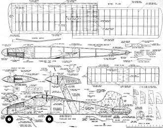
Full size plans for "Chariot" are on Group Plan
#457A from Hobby Helpers. 770 Hunts Point Avenue, New York 59, New
York (50c).
Notice:
The AMA Plans Service offers a
full-size version of many of the plans show here at a very reasonable cost. They
will scale the plans any size for you. It is always best to buy printed plans because
my scanner versions often have distortions that can cause parts to fit poorly. Purchasing
plans also help to support the operation of the
Academy of Model Aeronautics - the #1
advocate for model aviation throughout the world. If the AMA no longer has this
plan on file, I will be glad to send you my higher resolution version.
Try my Scale Calculator for
Model Airplane Plans.
Posted January 11, 2016
|