|
Pendulums
were used way back when to help keep free flight airplanes in a
controlled climb during the powered phase of the flight, and then
in a smooth glide back to terra firma. A weight was suspended from
a wire that pivoted on an axle, and a pushrod was attached to a
movable elevator. If the nose pitched up too much, the pendulum's
inclination to always point toward the center of the Earth would
move the pushrod in a direction to apply a little down elevator,
and vice versa for a downward pitch. I have planned to give it a
try some day, but as with so many other things, I just haven't gotten
around to it. Interestingly, there is still a form of free
flight glider flying in Germany that uses a weather vane arrangement
to control the rudder for keeping the airplane fling in a straight
line. The goal is to record the farthest distance possible. Pendulum
Pete
 Author-Designer
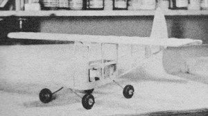
Keith Laumer until recently with USAF is now a U.S. Foreign Service
Officer stationed at the American Embassy in Rangoon. Shown is C/L
Pete. Author-Designer
Keith Laumer until recently with USAF is now a U.S. Foreign Service
Officer stationed at the American Embassy in Rangoon. Shown is C/L
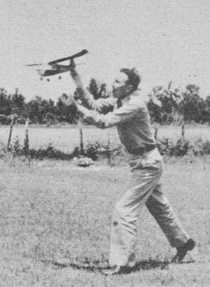
Pete. Your model lifts from the runway, eases
into a right turn, builds up speed and the bank tightens until the
wing is almost vertical; a crash seems certain - but not this time
... Pendulum Pete is at the controls! Power cuts, the plane rolls
out into a glide and drifts across the runway as if reluctant to
touch down; Pete is holding her nose up for a three-point landing.
On the next flight, with a little less right rudder, Pete will cruise
in the purposeful manner of a controlled airplane, with steady climb
and smooth approach glide. After a few free flights, a little
variety is in order; so out with Pete's control line wing, add a
set of lines, and you're airborne again in two minutes with a fast
and maneuverable sport job. And if you want to see how Pete will
act with a tricycle gear (or a four-wheeler, just for fun), pop
another gear in place - no tools needed. Pete flies nicely over
land or water with floats installed, coming in on grass without
a scratch. If you've never seen a realistic float model
touch down on water, bounce off. touch again with a dash of spray,
and swing into the wind to wait for a pick - up - you owe it to
yourself to let Pendulum Pete show you how it's done.
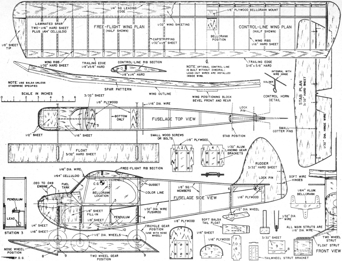
Free Flight Pendulum Pete
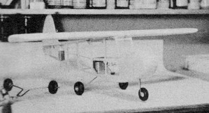
Three Wheel Pendulum Pete
Two Wheel Pendulum Pete
Four Wheel Pendulum Pete
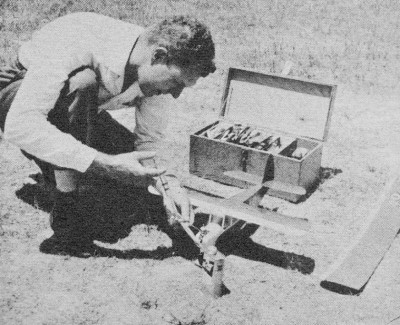
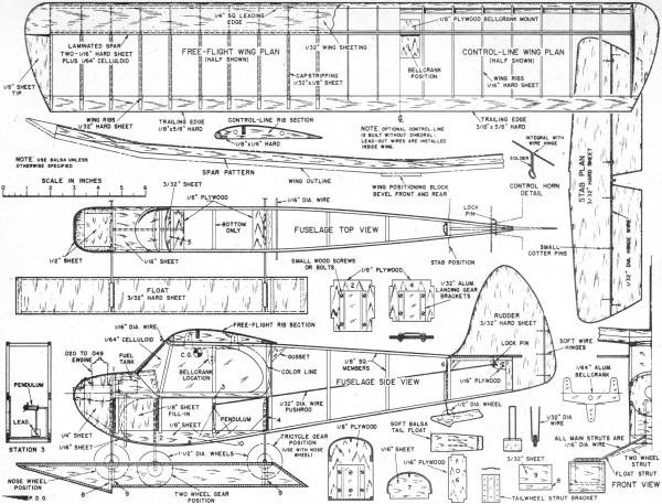
Construction? Simple! Fuselage is a simple box with three sheet
balsa parts and four plywood bulkheads. Tail assembly is sheet balsa,
and the two interchangeable wings feature one-piece tips and identical
ribs. Fuselage. Begun by
cutting bulkheads 1, 2 and 4 from 1/8" plywood, # 6 from 1/16" plywood.
Parts 5 and 10 are 1/8" sheet balsa, # 7 from 1/16" sheet balsa.
Aluminum retainer plates for convertible landing gear are formed
by clamping blanks of 1/32" aluminum over a strip of steel 1/16"
x 5/8", tapping with a light hammer. They are trimmed, drilled,
attached to bulkheads 1, 2, 4 and 6. (If fixed L.G. is desired,
simply lace wire to proper bulkhead, using No. 30 linen thread,
and cement binding.) Two sides are laid out using hard 1/8"
sq. balsa. Cut two of each piece, assemble first side over plan
(protect with waxed paper); second side is built directly over first.
While side assemblies are drying, bend pendulum support
from 3/32" brass welding rod to exact size indicated. Pendulum is
soft iron wire (a medium-size paper clip is ideal). Wire is wrapped
around support shaft eight turns. A loop is formed at one end, the
other trimmed to proper length. Lead 1/8" x 3/8" x 3/8" is soldered
to long arm. Washer is soldered to support shaft behind pendulum,
and pendulum retained by wheel collar or by pin inserted through
small hole drilled in shaft end. When thoroughly dry, sides
are removed from plan, sanded smooth before separating, and joined
on bulkheads 2 and 4, with plates attached. The firewall, part 1,
is drilled for radial mount or notched for beams, to fit engine
used. Mounting nuts are glued to rear of firewall or under beams
and retained by strip of balsa glued over them. Firewall is installed;
sides are joined at the rear (note bevel of rear posts). Parts 5
and 7 are assembled, 1/8" sq. cross pieces added. Gussets are glued
in place. Plywood plates are put on at front and rear of cabin roof.
1/16" sheet balsa planking is attached to bottom from bulkhead 1
to cross-member between stations. 2 and 3. First section of fuselage
sides is filled with 1/8" sheet balsa. Interior of tank compartment
is fuel-proofed and No. 1 Perfect Fuel Tank (or equal) installed,
after which add sheet balsa covering. Sheet balsa cowling
is built up, side pieces first, then top and bottom, finally the
nose. Allow rough cowl assembly to dry before shaping with sharp
knife. Entire fuselage should be carefully sanded and coat of clear
fuel proofer applied to planked surfaces. Depending on engine used
cowl may be detached as unit or cut along thrust line so only top
half is removable. Pendulum support is glued in place and
reinforced with strip of nylon glued over wire and to sides of 1/8"
sq. balsa members at station 3. Front and rear wing mounting hooks
of 1/16" wire are added. Entire fuselage, including planked surfaces,
covered with light silkspan, wet, and clear fuel proofed. Tail Assembly. Rudder and elevator are cut
from medium hard 3/32" sheet balsa and sanded to streamlined shape.
Rudder tab is cut from rudder and mounted using soft copper wire.
Movable elevators are cut from stabilizer and elevator hinge and
control horn wire bent from 1/32" piano wire. Locking pin plate
is cut from tin can, soldered to control horn. Small cotter pins
are slipped over hinge wire, and notches to receive them are cut
in elevators - front edges of which are grooved to receive hinge
wire, which is then glued securely. Cotter pins are inserted
in trailing edge of stabilizer. Elevator is clear doped and sanded
smooth. Push rod should be bent to exact length and engaged in elevator
horn before elevator is glued in place on fuselage. With fuselage
in horizontal position elevator should rest horizontally. Pendulum
arm may be bent slightly fore or aft to adjust this neutral setting.
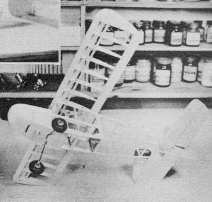
Glue rudder in place. Wing.
Free flight and control line wings employ identical leading
edges, trailing edges, spars. Ribs are basically similar but control
line ribs have two holes for lead-out wires and additional notch
for leading edge reinforcement. For free flight the spar
is built first. Two identical spars are cut out in four pieces each
from hard 1/16" balsa. A full-length spar pattern is cut from celluloid.
One set of spar members is assembled and glued to celluloid; the
other set is glued to other side of celluloid, forming three-lamination
spar with celluloid in center. When spar is completed rib
positions are marked and 24 ribs added. Leading edge of 1/4" sq.
balsa is next assembled over plan, marked, and attached to front
edges of ribs. Trailing edge, of pine or hard balsa, is cracked
to proper dihedral angles and attached to rear ends of ribs. Tips,
cut from 1/8" balsa, are added next and structure sanded preparatory
to planking leading edge. Hard 1/32" balsa is used to cover top
of wing from leading edge back to main spar.
This
planking is carefully cut to size and attached in four pieces. Center
section is covered from leading to trailing edge on both top and
bottom surfaces. 1/32" x 3/32" hard balsa cap strips are installed
to complete wing structure. Cap strips are glued first at leading
edge, then at trailing edge; care must be exercised to ensure their
contact with ribs full length. Entire wing is now carefully sanded.
Construction of control line wing is identical with that
of free flight wing except for additional leading edge stiffener.
It must also be noted that control line wing is flat and employs
one piece leading edge, trailing edge and spar. Top center planking
is not added until bellcrank is put in position. Plate of 1/8" plywood
is installed in center section to receive bellcrank. Lead out wires
are installed inside wing. Positioning blocks, cut from
1/8" sheet balsa to fit inside cabin roof structure, are glued to
underside of both free flight and control line wings. Special
bellcrank is cut from 1/64" aluminum and bent as indicated. Slots
for bellcrank arms are cut in underside of wing's center section.
Make sure controls work freely before covering top of center section
with 1/32" balsa. Wing is covered with light Silkspan, wet, clear
fuel proofed, sanded lightly. Landing Gear.
A complete set of landing gears for Pendulum Pete includes one
nose gear, one main gear (two wheels); a tail wheel, and two two-wheel
gears used together for a four-wheel gear, one being used with the
nose wheel for tricycle gear. In addition, set of floats may be
made and mounted on same struts as four-wheel gear, provided wheels
are secured by collars to enable them to be removed. Floats
are constructed entirely of 3/32" medium hard balsa. Aluminum mounting
fittings are bent from 1/64" aluminum, sandwiched between bulkheads
8 and 9, and 10 and 9, respectively. A small hole should be drilled
through mounting assembly and pin or bolt inserted to secure aluminum
firmly. Completed mounting assemblies are glued to float side. Other
side is added and bottom planks installed. Interior of each
float should receive two coats of fuel-proof dope and all joints
reinforced with glue. Top covering pieces should be sealed with
two coats of fuel proofer before being glued in place. Back plates
are added last, and entire pontoon carefully sanded. Floats are
given a coat of clear fuel proofer and final sanding before covering
with silkspan. Tail float is carved from soft balsa and 1/32" wire
strut glued in place. Finishing.
With all parts fuel proofed and sanded, entire model should
be sprayed with two coats of white fuel-proof dope. When thoroughly
dry, all surfaces should again be sanded lightly. Now for
the windshield. Since no two models are identical, it will be necessary
to make an individual pattern to fit yours. Use a piece of stiff
paper, such as a magazine cover, and after estimating position of
front wing mounting hook, punch a hole and center pattern on mounting
hook. Wrap pattern around sides, mark position of edges with pencil.
Cut out along lines and check fit. When pattern fits perfectly,
place it on sheet of 1/64" celluloid and trace outline with sharp
razor blade; crack and strip off excess. Install windshield, gluing
first at center; then bend around one side of cabin and glue. When
first side is thoroughly dry, glue other. Pendulum
Pete Bill of Materials 1/8" plywood 2" x 9" for
bulkheads, plates; 1/16" plywood 3/4" x 1 1/2", bulkhead; (3) 1/8"
sq. balsa (hard) 36", fuselage; (2) 1/8" x 1/4" balsa (hard) 36"
fuselage, C.L. wing; (1 1/2) 1/4" x 1/4" balsa (med.) 36", L. E.;
(3) 1/32" balsa (hard) 3" x 36", ribs, plank, caps; (1) 1/16" balsa
(hard) 2" x 36", spars, fuselage cover; (2) 3/32" balsa (med.) 3"
x 36", tail assembly, floats; (1) 1/8" balsa (med.) 3" x 15", wing
tips, fuse parts; 1/4" balsa (soft) 2" x 4", cowl sides and bottom;
1/2" balsa (soft) 2" x 4", cowl top and front; 1/8" x 3/4" pine
43", trailing edges; 1/32" aluminum 21/2" x 8", L.G. plates, bellcrank:
1/64" aluminum 1 1/8" x 6", float attach. plates; 1/32" piano wire
36", push rod, elev. hinge, tail gear; 1/16" piano wire 44", L.G.,
wing mounting hooks; 3/32" brass rod 6", pendulum support; 1/32"
soft steel wire 4", pendulum; lead 1/8" x 3/8" x 3/8", pendulum
weight; 1/64" celluloid 10" x 10", windshield; 1/64" celluloid 2
1/2" x 32", spar lamination; light Silkspan 2 sheets; small fuel
line 6"; clear fuel-proof dope 4 oz.; white fuel-proof dope 4 oz.;
colored fuel-proof dope 2 oz.; 6 small cotter pins; hinges; 12 bolts
1/16" x 3/8"; L.G. plates; (1) 1/4 oz. tank (Perfect #1); (7) 1
1/2" wheel (Perfect #34); 1/2" wheel (Perfect #30). Windows
must be masked off and another coat of white sprayed on front half
of fuselage. One-piece mask for windows may be made by tracing pattern
onto tracing paper, covering with tape and cutting out, after which
paper backing can be stripped from tape. A similar mask
should be made to cover entire front portion of model which is to
remain white. Planked portion of wing should be masked off, as well
as sides of floats. Final color finish is sprayed on entire unmasked
portion of fuselage, wing and floats, after which tape is removed
carefully to avoid tearing paper. Decal numerals can be added to
suit individual. Flying. First make
sure model balances as indicated. Then, with elevator lock pin installed,
hand-launch over grass. Correct any nose- or tail-heavy tendencies
by adding weight. When flat glide is achieved, remove locking pin
and try a low-power flight. Slight nose-heaviness will simply cause
model to drop a little more rapidly in the glide, although pendulum
will hold the nose up. Excessive tail-heaviness will cause rapid
up-and-down fluttering of tail. For control line flying three-wheel
gear is preferable to two. Control line wing is installed by first
sliding pendulum off support shaft and disengaging from push rod.
Push rod is then engaged in bell crank and wing attached by rubber
bands, wing positioning block fitting inside cabin roof to key wing
in position. When flying Pendulum Pete with floats installed,
do not attempt to ROW unless water is smooth. However, when hand-launched,
Pete lands easily even in choppy water. Always launch very gently
as a sudden lunge will cause pendulum to swing back and dive the
model into the ground. Full size plans for Pendulum Pete
are on Group No. 1257 from Hobby Helpers, 770 Hunts Point Ave.,
New York 59, N.Y. (35c)
Pendulum Pete
Plans
<click for larger
version>
Notice:
The AMA Plans Service offers a
full-size version of many of the plans show here at a very reasonable cost. They
will scale the plans any size for you. It is always best to buy printed plans because
my scanner versions often have distortions that can cause parts to fit poorly. Purchasing
plans also help to support the operation of the
Academy of Model Aeronautics - the #1
advocate for model aviation throughout the world. If the AMA no longer has this
plan on file, I will be glad to send you my higher resolution version.
Try my Scale Calculator for
Model Airplane Plans.
Posted May 20, 2012
|