|
Here
is the article for the Ryan M-1 Mailplane that I electronically
scanned from my purchased copy of the November 1969 American Aircraft
Modeler magazine, beginning on page 25. You might be able to scale
up the image below if you cannot find suitable plans for sale. The
article was written and plans drawn by Mr. Vic Harden. All copyrights
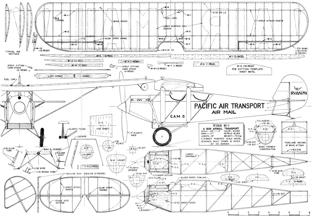
(if any) are hereby acknowledged. Ryan M-1 Mailplane
From this design the Spirit of St. Louis was developed. Rubber-powered
mod-el has details galore for the expert and clear instructions
for the beginner. by VIC HARDEN BEFORE 1926 few people
had seen an airmail plane up close. But about that time the government
began to award contracts to private firms to carry the mail. This
was the real beginning of our present day air-line companies.
Along with designs by Douglas, Boeing and others, was one
built by the Ryan Air-lines School of San Diego. The aircraft per-formed
well even with lower horsepower and a heavier Hispano- Wright engine,
in place of a Wright J4 engine originally specified. Known as the
Ryan M-1, the plane later became the M-2. Some were built with the
Risso, some with the J4, for airline com-panies in the West.

Model's structure features use of
card stock, bond paper for wing leading edge, and built-up ribs.
All curved outlines are laminated balsa strips. Fliesgreat
indoors or out.

Then Lindbergh picked Ryan to build his airplane. As history records
he was success-ful in 1927 on a long and lonely trip, from New York
to Paris. His Ryan number 29 was a descendant of the M-1 and M-2.
The similarity was evident between the M-l and the NYP Ryan used
by Lindbergh. Our rubber-powered model is the Risso-powered
version. It provides more nose length, giving a graceful and smooth
appear-ance. A number of photographs exist of this version of the
M-1 and M-2 as well as the J4 version. The American Airman Magazine,
Vol. 4, No.7, of July 1961, shows two M-1/ M-2 Risso versions.
General Aviation News Monday, March 24, 1969, carries a
picture of the M-1 now on display in San Diego. You can
build a full-detail-scale type, or a scale-outline type. Both types
require about the same effort and both will per-form well. My model
was a scale outline variety used to develop a larger diesel-engined
job. The amount of detail will affect the final weight.
Start with the wing since it is the most difficult part. Using the
patterns for the spars, front and rear, aileron and false spar and
centerline splices, each cut from 1/32" straight-grain sheet, make
two of each except the centerline splice pieces. The rib template
is cut from light gauge aluminum or tin. Use the template to cut
30 upper rib caps from 1/32" straight-grain sheet. Each rib should
be 3/32" wide. In addition, cut 1/32 x 1/8" strips for the lower
caps from the same material. The leading edge is 3/32" sq. and the
trailing edge is 1/16 x 1/4". Trace the shape of the tip
on a piece of cardboard about 1/16" thick. Cut out at the inside
line and use it to bend the 1/32 x 3/32" laminations to shape. Soak
the wood in hot water a few minutes, then bend it around the cardboard
form, holding the strips in place with pins pushed into any soft
mate-rial used as a flat base. Use an oven at 1250 F to speed up
the drying time to a half hour. Two sets are required. The
wing structure can be set up over wax-paper-covered plans. Trim
the forward ends of the lower rib caps to a 45-degree angle and
assemble them in place with the spars, trailing edge pieces and
leading edge strip. The upper rib caps are trimmed to match at the
lead-ing edge with a 45-degree angle cut, and to fair at the trailing
edge on the lower rib cap. Build the wing, including the ailerons,
as a single unit. Cut away the ailerons after the tips are completed.
This assures alignment. Now for the horizontal and vertical
surfaces. Make up the cardboard forms (same as for the wing tips)
and bend the 1/32 x 1/16" laminations into place on the forms and
dry as before. By now your wing tips should have dried and those
laminations can be glued together holding them in place on the form
to fix their shape. When the glue dries on the tips set them up
in place to fair with the leading and trailing edge pieces, block-ing
up in position. Glue all the contact posi-tions with spars and other
structure while still over the plans. Cut out the rib and
spar strip material for the tail surfaces from sheet stock; also
the fuselage material can be cut to required sizes. The tail surfaces
now can be laminated up on the form with glue and set aside to dry.
The wing halves can be taken up and checked for size and
condition. If OK, set them up on a level surface with approximately
a 3/4" block under each tip, adjusted so the center section of the
spar stubs lay flat and each tip is raised the same amount. Adjust
so that the splice webs will fit between the ribs with the leading
edge in a straight line tip to tip. Check everything for alignment
and position and then glue the splice webs into place on the spar
stubs. Now the tail surfaces, horizontal and vertical, can
be assembled. Shim up the outline bow shapes so they center on the
rib and spar depth. Cut the spars and glue into place over the plan.
The rib material is trimmed to fit each location and glued in place.
Set the assemblies aside to dry. The wing is now completed with
the lower rib caps at the tip locations cut and glued in place.
In-stall the center rib caps and two center-section trailing edge
ribs with the false spar at center. Cut and fit the gussets and
fairing blocks, gluing them in place as shown. Now the wing assembly
can be sanded smooth, leading and trailing edges and tips faired
and contoured to shape. Refer to the rib sections for contour. Install
the filler blocks at rear spar for lift strut attachment point.
The wing covering starts by attaching light bond paper from
the leading edge back to the front spar top and bottom. I use Titebond
glue to attach the bondpaper; a very light film on the structure
does just fine. The whole wing is covered complete, using your favorite
method and tissue. Water-shrink and block down to prevent a warp.
Also hold down for final drying of dope finish. The ailerons now
are cut away, then re-installed, using thin-aluminum sheet strip
for hinges glued in slots. Aluminum pop cans are a good source of
the thin aluminum. The final finish color is silver or aluminum
with black lettering on the underside of the wing as shown on the
plan. (More on color methods later, but remember the degree of finishing
is up to you.)
Take
up the tail surfaces and fair in the ribs, spars and edges to the
typical section shown on the plan. Sand the assemblies smooth, cover
with your tissue and water-shrink. Hold the parts in position to
pre-vent warping. Cut the control surfaces away, install the aluminum
strip hinges if you choose, then set aside. The fuselage
is the usual box-frame-type construction, using 1/16" sq. longerons,
forward fuselage uprights and diagonals. The aft section uprights
and diagonals are 1/16 x 1/32'" Build two side frames on the lower
plan and let the glue dry thoroughly. Mean-while, cut out the required
bulkheads, nose formers and webs shown on the plan from the stock
size required. When the side frames glue is dry, take them up and
join together with the formers F -1, F -2 and F -3, cross members
and C-l and C-2. Locate the sides on the plan top
view to keep the sides aligned. Complete the installation of the
diagonals. When the glue is dry, glue on the 3/32" side panel sheets
from the forward upright to the cowl block former (C-1) and up against
the horizontal web (C-2). The cylinder block formers (C-3) mount
on top of the web (C-2). The cylinder block sides (C-4) glue each
end to (C-3) and along their lower edge to (C-2). After the cowl
side panels are in place and the glue is dry, the lower cowl cover
of 1/8" sheet stock can be fitted and formed to match the cowl block
former (C-1) contour. Glue on the 1/16" sq. cowl stringers between
the two (C-3) formers, and add the 5/16" sq. soft balsa cylinder
head blocks to the length shown, then rounded on top. Check alignment of the formers and the fuselage. Place a straight-edge
or straight balsa stick about 10" long across the wing-mount position
at both front and rear spar positions. The edges of these should
be at the same level both sides of the center line on each end of
each stick or straight edge. Also place one stick across the area
where the horizontal will attach to the fuselage and sight to check
their being parallel. Correct any out-of-line condition; this will
affect the model's ability to fly well when completely assembled.
To complete detailing add the aft rubber peg support,
and its reinforcement - made from .010 or .015 plastic - glued to
the inside of the support on each fuselage side. The 1/16" sq. longeron
corners should be sanded to a radius along the length of the fuselage.
Also the top longerons, vertical and diagonal members above the
fuselage cowl for-mers F -2 and F -3 are sanded to a round section
as these will be exposed on the completed model. Assemble
the nose block unit from N-1, N-2, N-3, N-4 and N-5. Check its fit
into former C-1 and the alignment with the cowl sides and cylinder
block sides. Carve and sand N-3, N-4 and N-5 to form the contour
blending with the cowling sides and bottom. Also form the profile
or side shape shown on the plan. Note that the N-1 1/32" plywood
disc is set at an angle to give both right- and down-thrust. Hold
these angles as correctly as you can and drill a propeller shaft
hole 1/32" dia. in the center of the disc and square to it. The
propeller and thrust bearing will be held at the angle of the face
of N-1 disc when the rubber motor is wound. When the fuselage
wood work is done and sanded glue in place on each side of the wire
the stubs for the forward landing gear struts. Form the 1/32" wire
axle and .025 wire rear strut to the pattern shown on the plan.
Solder the 1/6" dia. brass tube cross-bars to the axle. Locate and
bind the axle wire assembly to the fuselage cross member at the
centerline. Position the rear strut wire at the cross member
and bind in place with thread. Align and insert the rear strut ends
into the axle cross-bar tubes. Check for position of the complete
assembly to the fuselage. Solder the rear strut ends to the cross-bars.
Now cement the axle and strut bindings to the fuselage. Make up
the two side-strut frames to fit on the wire stubs each side of
the fuselage. Drill two 1/32" dia. holes in each 1/16" dia. brass
cross-bar spaced as shown on plan, and solder 1/32" dia. wire stubs
in place. Cut 1/16" dia. aluminum-tube struts for each side, and
cement in place to form the side frame. Assemble onto fuselage wire
stubs. with the axle wire between the alu-minum tubes of the side
frame. Install a piece of plastic tube for a spacer on axle stub
so the wheel will not rub the cross-bar with an elastic shock absorber
thread tied in place. Install 1-7/8" dia. wheels. Cover
the fuselage with your tissue over all areas except the forward
upper cowl section under the wing mount, aft cockpit, and the wood
covered area of the engine cowling. Water-shrink and give one coat
of thinned clear dope. Spray the assembly with silver acrylic lacquer
(spray can type will cover well). Using silver Christmas paper,
not foil, cover the fuselage cowl, starting at the rear former.
Make flat patterns to follow the former shape and lay flat on the
fuselage frame sides. Proceed making one section between formers
at a time, gluing as you go. You can also cut panel sections to
cover the engine cowl section, simulat-ing the cowling divisions.
Attach these directly over the wood nose-section structure as far
back each side as the main gear for-ward-strut point. Add
the tail skid, the inverted vee braces shown at wing mount to cowl
top, cockpit-door outlines, fuselage lettering and door handles.
Fold up the radiator from silver Christmas paper and attach to fuselage.
Install rear landing gear strut fairings on the wire. Make up the
exhaust piping from plastic soda straws and balsa elbows. Now you
can choose the amount of detail you wish. Finish the cylinder blocks
and heads jet black and the exhaust system silver. All lettering
is black. With covering complete on the wing and tail surfaces,
spray finished the same as the fuselage with silver acrylic lacquer.
The wing and rudder can be lettered with black as shown - the rest
of the details are lip to you. Control horns, made from .015 plastic,
are easily made and installed. Gray thread is used for the rigging
and control wire. Cement the horizontal stabilizer and elevator
unit on the fuselage. Cut and cement the lower struts from fuselage
to the horizontal stabilizer, checking to keep it parallel with
the wing mount. Make a cardboard right angle template to set and
glue the vertical stabilizer and rudder in place, being sure to
keep the forward edge of the vertical on the fuselage centerline.
Install the vertical to horizontal brace wires from silver thread.
Cement the wing onto the upper fuse-lage longerons and cross
members. Check to be sure. the wing extends the same dis-tance each
side of the fuselage. Check for squareness to the fore and aft centerline
of the fuselage by using a stick to measure the distance from the
tail post to the same position on each side of the wing trailing
edge. The model is turned over for the fitting and installing
of the lift struts. Make up four struts as shown on the plan. Shape
and trim to fit the wing and fuselage. Assemble the card stock fittings
on the struts and paint silver. When dry, cement in place in positions
shown on the plan. If you choose, navigation and landing lights
can be in-stalled. Make the landing light tail cone from silver
Christmas paper and attach it to a 1/32" bulkhead. Cement on an
alumi-num-foil reflector surface and cover with a clear plastic
bubble formed to size. At-tach on under side of wing and install
the small side brace between the front spar line and the side of
the light assembly, as shown on the plans. Carve, sand and paint
the navi-gation lights from balsa and attach as shown. You
are ready to put in the rubber and start flying. Use a 12" loop
of 1/8" flat rubber for a light model up to 1-1/2 oz., or four strands
of 3/32" flat for a heavy model 2 oz. or over. The propeller can
be your own thing. carved from the raw block, or one of the excellent
plastic types for sale at your hobby shop. The 7" diameter seems
to work best under most conditions. A plastic spinner 1" in diameter
is fitted on the propeller. Assemble your propeller on a shaft through
the nose block. using a good thrust-washer assembly or bearing for
the best flights. Check the balance point indicated on the
plans. Some people are lucky. Most of us have to put a glob of clay
or some other mass to get the point to work out in the correct location.
You try that glide test. Hopefully all goes well and a few winds
are put into the motor for an added thrill. There she goes!
Everything looks OK. Now for that real try: a couple of hundred
winder turns and a minor adjustment and away he goes for a few rounds
by herself. The fun is just beginning. Since with normal care this
job won't destroy itself, many happy hours can be had learning all
that the model can do under varied conditions; both indoors and
out. Good luck and may fair weather be your !

<click for larger version>
Notice:
The AMA Plans Service offers a
full-size version of many of the plans show here at a very reasonable cost. They
will scale the plans any size for you. It is always best to buy printed plans because
my scanner versions often have distortions that can cause parts to fit poorly. Purchasing
plans also help to support the operation of the
Academy of Model Aeronautics - the #1
advocate for model aviation throughout the world. If the AMA no longer has this
plan on file, I will be glad to send you my higher resolution version.
Try my Scale Calculator for
Model Airplane Plans.
|