|
It would be difficult to find a more perfect aerobatic scale biplane
for control line flying than the Waco Taper Wing (WTW). Its solid
frame, near-zero dihedral in both wings, and nearly symmetrical
airfoil is just what the serious stunt flyer needs. Construction
is standard built-up stick and sheet balsa framing members and Silkspan
and dope covering. Today, you might choose to cover the Taper Wing
Waco with Monokote, or even
Coverite 21st Century Fabric if you want an authentic fabric
look that is still iron-on. Originally designed for a .30-size glow
engine, the model could easily be converted to electric power.
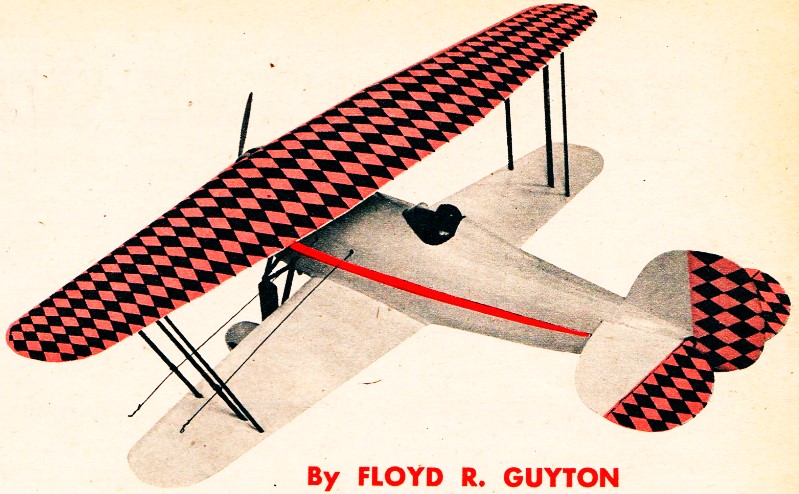
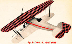
Taper Wing Waco
By Floyd R. Guyton
A grand' old bipe, favorite of many a famous stunt .pilot,
returns as a slick control line flying scale powered with .29 to
.32 engines
If you were old enough to tie your own shoelaces when "Lucky
Lindy" made history in 1927, then you might recall the era of the
stunt biplane, exemplified by the Waco Taper Wing.
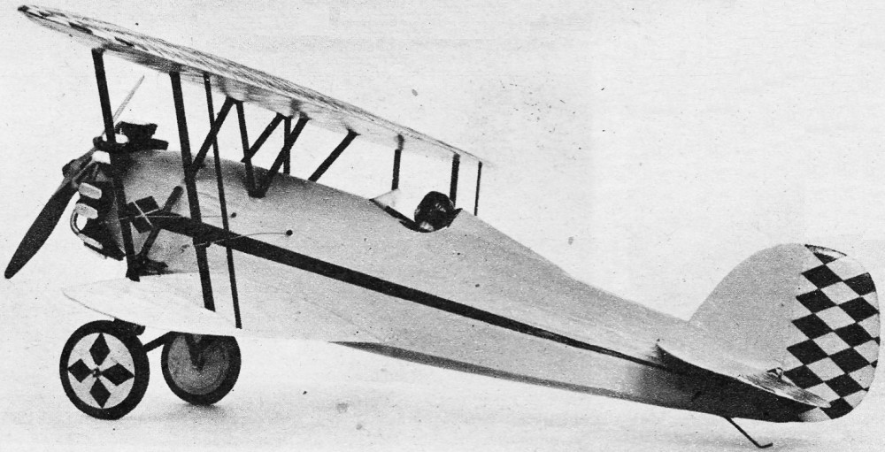
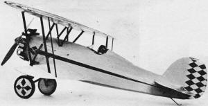
Even if you can't remember "the good old days" you can see what
a fine model this Waco is for stunting or for real detailed scale
flying. With no apparent dihedral, an almost-symmetrical airfoil,
and with its landing gear well forward, the WTW makes. an excellent
subject for U/C work. The Taper Wing, with its generally clean shape
and efficient tapered wings, was a great improvement over its predecessor,
the Waco 10.
Two models made by the author logged more than 150 flights, with
one model taking stunt and scale honors in the same contest. The
hot rock stunters can go easy on the super-details for a lighter,
more maneuverable ship. But loading the ship down with wheel pants,
cowl ring and such will not take the edge off its stunting ability
- it will still turn inside the other scale jobs and match some
of the flying barn doors in intricate acrobatics.
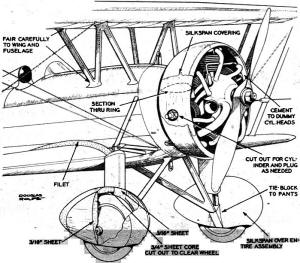
Testing should be done with the usual balloon type wheels, the
home-made scale type being saved for competition work. If wheel
pants are used, stock wheels can be employed, as they will not "show"
and a lot of work can be saved. Remember, with or without cowl and
pants, the job is still true to scale, as the prototypes were flown
both ways.
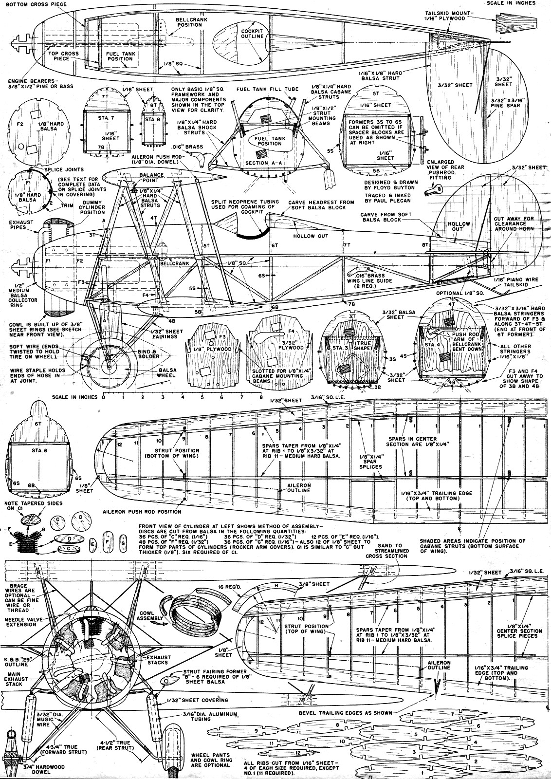
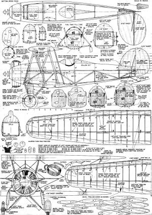
Now let's get a-building. Grab some 1/8" square balsa, but hard.
The basic framework can be tossed together as per the side view.
Allow the longerons to project slightly forward of Station 3, as
they fit into notches in F3. Once all the required cross braces
and diagonals are in place, allow the cement ample time to dry thoroughly
and remove from workbench. Building both side frames at once insures
exact duplication, so play safe and do it that way.
Use a thin razor blade to separate the two frames and start assembly
in the orthodox manner, tail-first. Work for ward carefully, checking
each frame for squareness as you go along. Note that the cross pieces
at Station 3 are not equal, due to slant. If desired, diagonals
at each station will help rigidity immensely, especially at Stations
5, 6, and 7. Hard 1/16" x 1/8" balsa is fine for this; it can be
left in permanently if not in the way of the push-rod, or cut out
when the fuselage is partly covered and has greater torsional rigidity.
The plywood bulkheads F3 and F4 can be slipped in place now and
cemented securely. Be sure to get all the holes cut out or drilled
through F3 and F4 before assembly.
The engine bearers can be slipped in place and cemented next.
Note that the upper bearer is longer - extending beyond the rear
of F4 to provide mounting space for the bell crank. The bottom of
this bearer is cut away to provide a horizontal surface for mounting
aforesaid bellcrank which, incidentally, protrudes through F4 (see
gourd-shaped hole made for this). Note that the push-rod arm of
the bellcrank is bent down somewhat to clear the upper cross-brace
at Station 4. Try to assemble as much of the control system as possible
in the early stages of construction, as hooking up the pushrod to
the bellcrank and other similar jobs are difficult once the stringers
and covering have been practically done. This applies to the lead-out
wires also.
The unorthodox position of the engine, with one engine bearer
under the crankcase lug and the opposite bearer over the lug may
seem unnecessarily complicated, but it is a fine way of hiding the
K&B .29 and providing space for a fuel tank of moderate size,
mounted in an ideal position. The usual upright position of a .29
in this ship necessitates running the engine bearers right through
that area where the tank should be - level with the needle valve.
However, for some compact engines like the Forster F-29 it shouldn't
be much trouble to "pad" the front of F2 with a slab of 3/8" plywood
for a radial type mounting for even greater latitude in positioning
the tank. In the event that you rework the nose section for radial
mounting, remember to beef up the construction enough to compensate
for the absence of engine bearers. And leave the bellcrank where
it is, regardless of what rework you do in other departments.
After bending the landing gear to shape, install as follows:
front (axle) strut, fastens to rear of F3 with spade. or "J" bolts,
rear struts are wrapped and soldered to front strut near axle, with
rear upper ends landing on the front bottom face of F4 (note holes
to receive same). Try to make all bends possible before installation
and remember that the true lengths are given in the front view and
cannot be measured or "lifted" from the full-size plans.
It won't hurt for the L.G. assembly to be installed so that there
is a little tension between the rear struts and F4 to keep the strut
ends in their respective holes. Allow the strut ends to project
about 1/4" past the rear face of F4.
The tailskid is bent up as per the plans and "sewn" to the 1/16"
plywood mount with fine wire. Cement liberally. Then cement assembly
to top surfaces of the bottom longerons. A vertical brace can be
added for safety's sake at the rear of the mount, but be sure that
it is not in the way of the horn or pushrod. The fuel tank should
be installed now, generously cemented and braced against shifting.
The top formers 1T, 2T, 3T, etc., are now added and the stringers
slipped into the notches. Hard. 3/32" x 3/16" stringers are used
forward of F3 and on the top formers 3T, 4T, and 5T, where 1/32"
sheet balsa covering is to be applied, with 1/16" x 1/8" hard balsa
stringers used elsewhere. The 3/32" x 3/16" stringers butt up against
the front of 6T,with the 1/16" x 1/8" stringers being used from
6T of the tail post.
Although the area over the stabilizer was sheet-covered in the
original model, many will prefer the simpler expedient of using
a carved block, hollowed out for lightness.
This block can be spot-cemented and carved after the horizontal
tail surfaces have been installed. Once hollowed, it can be cemented
on permanently, followed by the rudder surfaces. Nothing unusual
about the tail construction - just plain 3/32" sheet. But do cut
out clearance for back-travel of the elevator horn. Note the simple
but compact pushrod fitting for the elevator horn.
Once the balance of formers and stringers are in place, covering
may be started. The 1/32" sheeted areas are applied in the following
sequence: first, a narrow strip of 1/32" sheet is trimmed to fit
between the top stringer and the stringer adjacent to it. Rubber
bands around the fuselage should hold it snug against formers and
stringers after the cement is applied to hold the sheet against
the top stringer. The other edge, along the next stringer, is left
loose, so another sheet can be slipped under the .rubber bands.
A razor held against the edge of the first sheet can cut and duplicate
the trimmed edge to the underlying sheet. Of course, the rubber
bands will have to be shifted to avoid cutting them.
Thus, when a sheet is trimmed on both edges, only the high edge
is cemented in place - the low edge forms a pattern for the adjacent
sheet. And so the covering progresses downward from the top stringer
till all the side is done. If the wood you have on hand is "uncooperative,"
you can coax it along to fit any compound curves by dampening the
exterior face and by using thin cement on the interior surface to
draw it around. Put aside just long enough for the curve to "set"
slightly, then install.
It will be much simpler to do the work in short longitudinal
sections - in other words, don't attempt to cover too long a stretch.
Short pieces, from former to former will go on easiest.
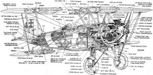
Complete building details are available on the full-size plans.
Waco Taper Wing Plans
Notice:
The AMA Plans Service offers a
full-size version of many of the plans show here at a very reasonable cost. They
will scale the plans any size for you. It is always best to buy printed plans because
my scanner versions often have distortions that can cause parts to fit poorly. Purchasing
plans also help to support the operation of the
Academy of Model Aeronautics - the #1
advocate for model aviation throughout the world. If the AMA no longer has this
plan on file, I will be glad to send you my higher resolution version.
Try my Scale Calculator for
Model Airplane Plans.
Posted March 6, 2015
|