|
Airplanes
and Rockets website visitor Peter I. wrote to ask for the article
on Jim Wilmot's Warlord to be scanned and posted. The model, which
appeared in the October 1973 edition of American Aircraft Modeler
(predecessor to Model Aviation) was designed specifically to compete
in FAI events. It features a molded fiberglass fuselage and built-up
wing and control surfaces. The stabilizer is of the all-flying variety
(aka stabilator). A SuperTigre 60 Bluehead engine was used in the
original.
Warlord Article & Plans
 by Jim Wilmot by Jim Wilmot A graceful and thoughtfully designed contest
pattern plane. Flies great in mile-high Denver - should be fantastic
at sea level!

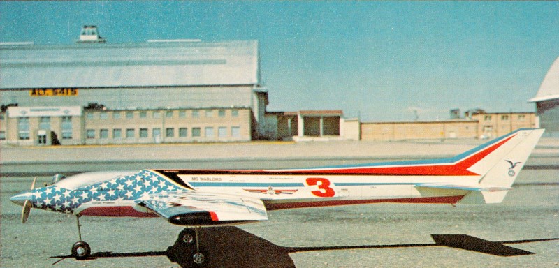
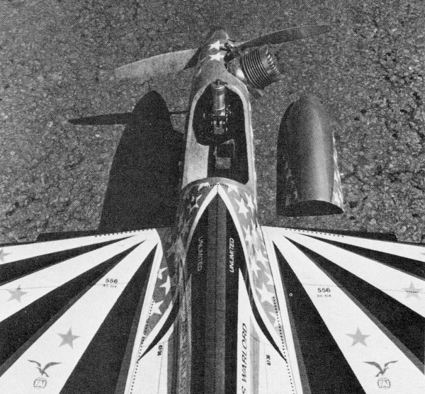
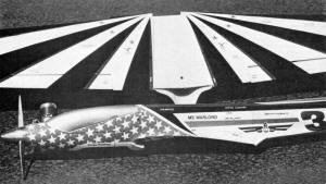
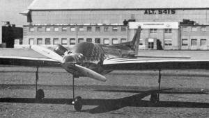
Minimum frontal area and flowing lines help get the most
out of the Warlord's engine/propeller. Sits high on the
retract gear for easy rough and grass field operation.
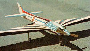
The best way to enjoy good flying at high altitudes as in
Denver is to have a lightweight plane. With all-balsa construction,
this bird can weigh only 6 1/2 lb. even with full-house,
fuel, a big 60 and retracts.
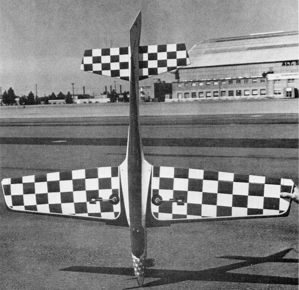
Control surface areas are large; ailerons can be lowered
for landing flaps. Note the highly recommended stall strip
on the wing near the fuselage.
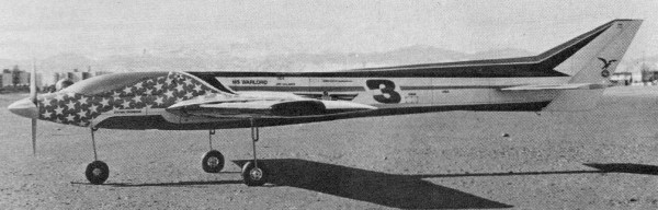
Heavily contoured fuselage is such that power can be utilized
efficiently.
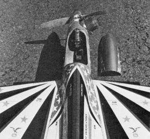
The wheel, when retracted, is partially out in the breeze;
a big fuel tank fits easily.
There's a lot of room in front even with retracts.
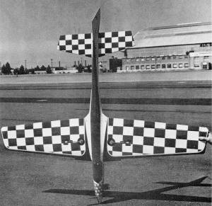
No wing keying dowel is needed here. Fuselage wraps around
the wing leading edge and the fillets fit on the "step"
at the center of the wing (see text).
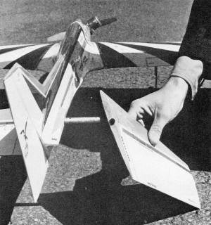
All-moving stabs are becoming popular. The author first
tried them successfully in his Warlock design (November
1972 AAM). Control is smoother with less drag; parts are
removable for easy transportation. |
The Warlord was designed to do only one thing: to win in FAI competition.
Initial drawings were completed only after intensive study of the
machines flown at the 1971 Internationals. From the information
gleaned from this study, future trends were extrapolated and all
of my past ten years of competition savvy was smoothly 'blended
into one competent design. Strict parameters for design
were set up in order to achieve perfection. Consistency is first
and foremost. Perfection of aeronautical design means nothing if
the guidance, propulsion, or retraction systems are not on the same
level of perfection. The old adage that the weakest link determines
the strength of the chain seems apropos. To this end, Pro-Line,
Supertigre, and Rom-Air were chosen respectively. Consistency
is the name of the game in that very often driving some 500 mi.
to a contest, only three flights for the weekend will be allowed:
two on Saturday and one on Sunday (and that's rough when you only
get one flight in a day!). Therefore, there is absolutely no room
for mistakes. Every flight has to be the best one of the meet. This
principle must also be kept in mind during construction, for a slipup
in assembly may (and probably will) blow a contest. Modern
RC competition history may be divided into four main categories;
Smog-Hog, Taurus, Kwik-Fli, and post Kwik-Fli era. In this last
era, almost any aircraft has the capability of winning any contest;
there is no No. One design - they all fly pretty much alike.
Therein lies the rub. An old element has increased in importance
- showmanship. Performance is now simply a given factor;
the variable exponent takes the form of presentation and pilot skill.
The game has inadvertently developed into a form of one-design competition.
To win at this kind of game, one must stand above the competition.
The meet must be won before the flight begins through the use of
an impressive-looking machine and a tremendous amount of practice.
Here are some of the principles set up in the design stages
of the Warlord: The airframe must be such that power can be utilized
as efficiently as possible. It should be smaller than the Warlock
(my design featured in November 1972 AAM) and yet appear to be the
same size as the current trend. Appearance should be given same
priority as performance. To achieve these goals, one main
point was kept in mind at all times: cut drag wherever possible.
I chose a 12 1/2% somewhat laminar section, a heavily contoured
fuselage and employed a flying stab. All information was fed into
a CR-193 "computer" (modular exponents) and it was determined that,
at periods of barometric pressure 29.98, 67° temperature, 34°
dew point and 45% humidity, optimum performance would be achieved.
(These are the forecasted climatic conditions for the 1975 Internationals.)
Also it was discovered that control reversal would be evident at
147 mph. (The sound-barrier effect, like the Reynolds effect, reacts
differently on models.) Therefore a flying stab was a necessity.
The fuselage contours plotted out by the CR-193 were not possible
if a normal balsa framework was used. So a fiberglass mold was machined
out of platinum-aluminum alloy noted for its resistance to warpage.
(I wouldn't put you on now, would I?) Here I should warn
you about the treacherous pitfalls that may ensnare the builder
as he attempts to mimic my melange. Construction
Fuselage: First of all,
note that the construction has been altered from fiberglass to wood
to simplify the chore. It has also been widened a smidgen to allow
more room for equipment. (Some alleged authorities accuse me of
designing too thin a fuselage.) The basic structure should
cause no real trouble if it is built on a jig. (The new A-Justo-Jig
would probably work nicely.) Use a long, flat pine board with squaring
blocks. Note that the fuselage wraps around the front portion
of the wing leading edge, which eliminates the need for front wing
bolts or dowels. The bottom hatch for the wing is cut out after
the fuselage is hacked out. Also, each wing servo (retract and aileron)
is mounted on the bottom of the wing center section. Thus aileron
trim can be adjusted without taking the entire wing off the fuselage,
and the Rom-Air retract switch can be inspected easily. The rudder,
elevator, and throttle servos are mounted on a 1/16" ply tray, which
takes up very little room, can be fitted into tight spaces, and
removed in about half a minute. For this kind of installation, use
Kwik-Link connections on all servo output disks. The canopy
and cowl are made from fiberglass; the canopy may also be molded
from clear plastic. The molds can be made in the wood-fiberglass
tradition, or carved from styrofoam using the balloon-forming process.
The Wilmot lost-mold process is another method in which
a plug is made from wood or finished styrofoam, and a thin coating
of plaster is spread on the outside and left to dry. Then the plug
is slipped out of the plaster, and a coating of matte fiberglass
is placed in the plaster cavity and left to cure. Finally, the plaster
is simply broken off with a blunt instrument (such as a size D sledgehammer)
which leaves a quicky fiberglass cowl. The firewall is a
little tricky. Both the engine backplate and the Rom-Air nose gear
must be bolted on their respective sides. Believe it or not there
is room with some left over if they are bolted as shown on the plans,
and a nut-plate is slipped over the backside of the Rom-Air unit.
4-40 bolts go into this nut-plate from the front of the firewall
and are countersunk so that the engine backplate mount can be bolted
flush to the firewall. The engine mount must be removed
to tighten up the nose gear bolts. These bolts should be secured
temporarily with Titebond to prevent loosening from vibration. A
1/8" rubber spacer can be placed between the firewall and the nose
gear to cut down on the vibration picked up by the gear.
Wing: Again, this is a relatively straightforward
structure and should be jig-built. One tricky item with which to
deal is the "step" I have built into the center section of the wing.
This step is included so that the large fuselage fillets can blend
smoothly into the wing. Normally a very thin fillet edge is used;
however, this was impossible in the fiberglass version. As a result
the "step" was developed which also serves to keep the wing from
shifting and prevents oil from seeping into the servo areas.
Be sure to fiberglass the center section with medium-weight
cloth and a good resin such as Whitewater. This is just about all
that holds the wing together, but it seems to be more than adequate.
Wheel wells for the retracts can be made out of Styrofoam
cups, from Ajax cans or any other cardboard tubes that give clearance
for the wheels. The aileron torque rods are of 1/8" music wire,
and are supported at each end by aluminum bushings. The wing is
an open-bay type and should not be fully sheeted if the FAI wing
loading is to be observed. Stall strips are made of 1/2"
triangular stock, and faired smoothly into the center leading edge,
just outside the fuselage. They serve two purposes: they cause the
center section to stall before the tips (which is mandatory at high
altitudes and heavy weights); and they keep the wing from shifting
because they snug up against the fuselage. Ailerons can
be carved out of sheet, or built up from 3/32" sheet. Wing tip weight
will be necessary to counter the offset engine and muffler combination.
Flying Stab: This particular flying
stab is identical to the very successful Warlock. Out of six aircraft
with this stab, I've had no trouble with any of them, and one ship
is going on its third year of flying. The heart of the system is
the 1/2 and 7/16" brass tubes which are the pivots.
The
basic stab is carved out of a single piece of 1/2" sheet balsa,
with the 1/2" tube epoxied in place to serve as the high point of
the airfoil. Unbelievable as it may seem, a true stab can be carved
by just using a rasp and sanding block. Once the shape is achieved,
the stab center section is cut out with a band saw, through 1/2"
tube and all. Then the 7/16" tube is inserted in the center section
tube and S-3 is soldered to the 7/16" tube after the clearance holes
have been cut out of the 1/2" tube with a Dremel tool. At this point,
you should have the center section, with a full-length 7/16" tube
running through the 1/2" tube, and a tiller that rotates the 7/16"
tube. The flying stab halves are fastened onto this 7/16" tube by
3/8" sheet metal screws. Finally, epoxy the stab center
section onto the fuselage and install the aileron-type tiller on
the tiller bar. Be sure to use a straight-line fiberglass push rod
and a good slop-free servo on the flying stab. While there are no
flutter tendencies, try holding one half out of a car window doing
70 mph and notice how much force is present. If the stab is steady,
very little effort is needed to rotate it, but a good amount of
effort is required to hold onto it. Make sure the center section
is epoxied on solidly and fillet well. Finish the stab halves with
fiberglass resin to prevent warping. At present, I still
have Number. One Warlord which weighs 8 1/2 lb. with fuel, a much
thinner wing (10%) and a Webra 61. I t has a tremendous amount of
flight time behind it and I have never had any stab problems. Trust
me it works. The fruits of my labor were evident at the
1972 Nationals. I left Colorado with a brand-new Warlord that had
been flown a total of 5 1/2 min. I thought that if I didn't fly
my No. One ship before the NATS, I couldn't possibly crash it as
had happened before at the last two Glenviews due to circumstances
beyond my control (obviously a theory born out of desperation).
Once at the NATS, I found that the Warlord's uniqueness had charmed
the judges as I was receiving 1-2 points per maneuver (which I didn't
deserve on an untrimmed aircraft). Unfortunately, I suffered a mishap
right in the middle of the NATS not just before it, and as a result,
I had to leave Warlord No. Two in a trash can. (That was before
I switched to Pro-Line.) C'est la guerre. Who knows what evil lurks
at this year's NATS. See you there!
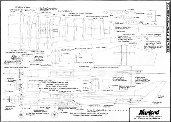
Warlord Plans<click
for larger version>
Notice:
The AMA Plans Service offers a
full-size version of many of the plans show here at a very reasonable cost. They
will scale the plans any size for you. It is always best to buy printed plans because
my scanner versions often have distortions that can cause parts to fit poorly. Purchasing
plans also help to support the operation of the
Academy of Model Aeronautics - the #1
advocate for model aviation throughout the world. If the AMA no longer has this
plan on file, I will be glad to send you my higher resolution version.
Try my Scale Calculator for
Model Airplane Plans.
Posted June 26, 2013
|