|
Website visitor Adrian C., of
Moncton NB, Canada, wrote to ask that I scan and post the article for a catapult-launched
free flight glider model of the Zlin Akrobat. It appeared in the September 1971
edition of American Aircraft Modeler. Written by well known and frequent
contributor to the "For the Tenderfoot" series in AAM, this version of
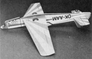
contest-winning full-size Akrobat has an 11" wingspan and the plans provide a high
level of detail and realism for such a small model. Its bright scale-like red and
white covering scheme is particularly attractive. I took the liberty of adding
color to the plans.
Zlin Akrobat: For the Tenderfoot
 By Bill Hannan By Bill Hannan
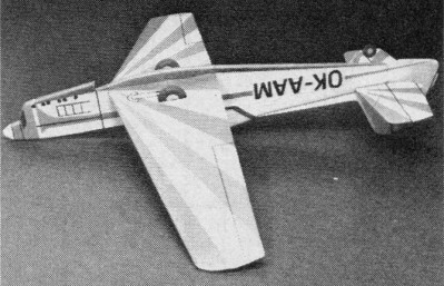
With colorful trimmings, this profile model becomes almost three-dimensional.
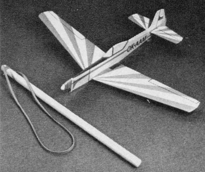
Catapult launching gives it long flights even in small hands.
Here's a small, simplified model of the famous Czechoslovakian aerobatic aircraft,
which has appeared in so many international events. This glider is based on the
Zlin 526 AS Akrobat and the information is from a Czechoslovakian aviation publication.
Colored tissue is used for striped patterns, a ballpoint pen
draws the lines.

The launcher dwarfs the model.
Profile models are easy to build, yet offer a chance to develop techniques which
are useful in more advanced models. So "Czech-out" the drawing, grab some wood and
get started!
Construction
This model should be constructed from fairly hard balsa, except for the tail
planes, which should be made from lightweight stock.
Fuselage: Trace the outline of the body onto thin paper which,
when cut out, will serve as a pattern. Transfer the outline by drawing around it
with a very soft pencil, onto a sheet of unwarped 1/8" sheet balsa. Cut the fuselage
to size, being particularly careful to keep the wing and stabilizer openings in
their correct positions. The section beneath the wing may be removed, to be trimmed
and replaced later, after the wing is in place.
Give the fuselage a thorough overall sanding and gradually taper the aft portion
(as viewed from the top) down to 1/16" thickness, where the rudder will be attached.
All of the corners may be rounded, except at the top and rear areas where the fin
and rudder will be mounted. Cut a slot in the bottom of the fuselage to receive
the tailwheel unit, which is cut from thin plywood.
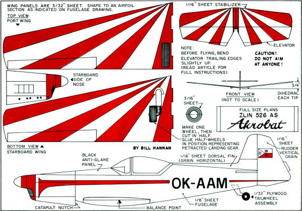
Wing: The wing panels are cut from unwarped 3/16" sheet balsa.
Using the pattern system, transfer the outline to the wood and trim to shape. Do
a precision job on the notches because they contribute greatly to the strength of
the dihedral joint. After cutting the wings to outline, shape them to the airfoil
section shown on the plan. A sanding block is the best tool for this operation.
Fit the two panels together at the correct dihedral angle. Probably a little
trimming and sanding will be required for a good snug fit. Pre-glue each side by
rubbing a small amount of glue into the joining areas. Apply a second coat of glue,
place the parts together at the correct angle, and put aside to dry completely.
A sheet of Saran Wrap will prevent the wing from becoming a permanent addition to
the work table.
Empennage: Patterns of the tails are used to transfer the outlines
onto 1/16" sheet balsa. In the fin and rudder parts, note the direction of the grain,
which contributes to their strength. Sand the parts to a streamlined section, except
for the actual mounting areas.
Wheels: The retracted landing gear strut assemblies are drawn on paper and glued
in position. Only a single wheel need be made. Cut and sand it to shape from balsa,
then cut it in half to represent the retracted wheel. Paint the tires with Hot Rod
Primer. It looks a great deal more like rubber than the usual flat black.
Decor: Obviously, the model simply could be glued together and
be ready for flight. But, nothing looks more unfinished than a plain balsa aircraft.
So, take extra time to add the coloring which will really light up the natural good
looks of the miniature Zlin Akrobat. The easiest way to do this is before assembly,
when the parts are still -flat on the work bench.
Since Zlins have been employed by aerobatic pilots from various countries, many
color schemes are available. Color photos of these machines have appeared in several
aviation publications, so select one of them as a guide. Or, invent your own! Ours
is an amalgam of East German, Czechoslovakian, and imagination. The OK is legitimate
Czech, but the AAM is simply the initials of our favorite magazine!
Finishing: Give all parts a coat of clear dope, applying it
quickly to both sides of each part, otherwise warping may occur. The parts must
stand on edge while the sides are drying, so lean them against a drinking glass,
and sticking will be minimized. Plasticized dopes, such as Sig Litecoat, will also
help prevent distortion. After the first coat has dried, lightly sand each part
to remove the balsa fuzz. Then apply two more coats of thin clear dope to all surfaces.
The color stripes are cut from Japanese or art store tissue, which is available
in a large variety of colors. A sharp blade is a must to obtain clean edges when
cutting tissue, and a metal straight-edge is the best guide. By cutting two layers
at a time, decorations for both sides can be made at once. Taping the tissue down
taut to a sheet of cardboard will help prevent wrinkling and tearing while cutting
out the decorations. The markings letters may also be cut from colored tissue or
paper.
Place each decoration over its correct location on the part, then flow dope thinner
right through the tissue. If sufficient clear dope has been applied to the part,
the thinner will soften it enough to firmly hold the decoration in place. Sometimes
a little gentle rubbing will be needed to snug the edges down, especially around
curves. On tight radius corners, a drop of water applied with brush or fingertip
will soften the tissue enough to allow it to conform to the shape. Be careful not
to over-wet the tissue, or it may tear. The tissue technique may seem a bit tricky
at first, but once it is mastered, it will be useful for all sorts of modeling projects.
After all of the decorations are in place, the various outlines, such as the
aileron, may be drawn on with India ink and a drafting pen, or applied with chart
tape. This very narrow tape may be obtained at art supply stores, or at some hobby
dealers, where it is generally known as slot car striping tape.
Assembly: Glue on the tailplanes in their correct positions
in relation to each other. Next, fit the wing into the fuselage opening, which may
require a bit of trimming or sanding to achieve a good fit. Glue in the wing, being
generous with the glue, in this high-stress joint. Fit the lower fuselage piece
into place, sanding to fit, if necessary, and glue well. The wheels may be added
to complete the model.
Flying: Catapult gliders are a special breed and require extra
care in preparation if they are to perform efficiently. Briefly, the problem is
the very great difference in speed between launching and gliding. Thus, tiny adjustments
which may have little effect when the model is hand-glided, may have quite drastic
effects when the model is catapult-launched.
Be certain that none of the surfaces is warped. If warps are found, they may
be removed by holding the offending part over a steaming teakettle, bending it a
bit beyond the desired location and then allowing to cool. Keep in mind that changes
in temperature at the flying field may cause the warps to reappear, so check on
them if the. model behaves strangely after having been adjusted.
The model should balance near the point indicated on the plan. A single finishing
nail was sunk into a drilled hole in the nose of our model. Final minor changes
in ballast are made with modeling clay. For the first flights, it is a good idea
to put a small glob of clay on the lower nose, where it can serve as a shock absorber.
A few hand glides should establish the need for addition or subtraction of weight.
Also, if necessary, the elevators may be adjusted by slight bending. If the model
should persist in falling off on one wing, a small lump of clay added to the opposite
wing elevator setting. More up elevator means more nose weight (assuming the model
is already correctly balanced). As the elevators are lowered, a slight amount of
nose weight usually can be removed. In order to achieve consistent results, test
flying should be performed on a calm day. Once the launching and adjustment techniques
are learned, the model can be flown in wind also. If possible, do test flying over
grass or weeds, which will help compensate for any pilot error.
You may want to experiment for best results, but our system is as follows. The
catapult is a hardwood dowel 10" in length, 3/8" diameter. Smaller diameter sticks
are not recommended, because they may break at exactly the wrong time - which really
smarts! To the dowel tie both ends of a piece of 1/8" flat rubber about 16" long.
Our model is adjusted to glide in a gentle left circle, by means of wing tip
weight or very slight left rudder bending, or both. The tip should cure the problem.
Adjustments made with clay ballast are safest, since their effect is virtually
constant regardless of speed, as compared to surface bending, which causes distinctly
different effects with speed changes. Ideally, the model should be flown with the
elevator at 0 degrees in relation to the wing. However, this setting allows almost
no margin for error in launching. That is to say that the model will be unlikely
to pull out of a steep dive at low altitude. On the other hand, if too much up elevator
is warped into the tail, the model will simply loop and will not gain enough altitude
for good duration flights. Therefore, we suggest starting with a small amount of
up elevator. Bend the trailing edges up perhaps 1/16" or so; then, as test flying
and launching practice proceeds, the trailing edges may be lowered slightly.
A direct relationship exists between the amount of nose ballast required and
the model is launched in a fairly steep banked attitude to the right, and upward
at perhaps a 30-degree angle. The model is gripped directly above the tail wheel
with the right hand, while the launching stick is held with the left. Pull back
and release. Not pulling back far enough can be hard on the model until it has been
adjusted, since it may stall at low altitude, without time to recover. Conversely,
if the model is badly out of adjustment, too hard a launch may cause it to loop
over and into the ground at balsa-crunching speeds. Try for a happy medium at first
and increase the amount of stretch as you go along. A banked model may loop horizontally,
which is less apt to do damage than the same model launched with the wings level.
When flying on windy days, we have had best results when launching across the wind,
rather than directly into it.
We think you will enjoy catapult gliders, and if you would like to participate
in postal contests with other Tenderfoot modelers in other parts of the country,
full details plus a delightful newsletter are available free from:
<redacted>.
Zlin Akrobat Catapult Launched Glider Plans
Notice:
The AMA Plans Service offers a
full-size version of many of the plans show here at a very reasonable cost. They
will scale the plans any size for you. It is always best to buy printed plans because
my scanner versions often have distortions that can cause parts to fit poorly. Purchasing
plans also help to support the operation of the
Academy of Model Aeronautics - the #1
advocate for model aviation throughout the world. If the AMA no longer has this
plan on file, I will be glad to send you my higher resolution version.
Try my Scale Calculator for
Model Airplane Plans.
Posted January 9, 2024
(updated from original
post on 4/14/2014)
|