|
 John Burkam was one of the few true pioneers
in free flight and particularly radio controlled model helicopters. His experiments
date back into the 1940s. His rubber-powered
Penni Helicopter appeared in the
January 1970 issue of American Aircraft Modeler. Also, he covered the 1972
and 1974 helicopter Nationals competitions in American Aircraft Modeler (RC Helicopters at the Nats,
December 1972 AAM | RC Helicopter
Nats, January 1974 AAM). John Burkam was one of the few true pioneers
in free flight and particularly radio controlled model helicopters. His experiments
date back into the 1940s. His rubber-powered
Penni Helicopter appeared in the
January 1970 issue of American Aircraft Modeler. Also, he covered the 1972
and 1974 helicopter Nationals competitions in American Aircraft Modeler (RC Helicopters at the Nats,
December 1972 AAM | RC Helicopter
Nats, January 1974 AAM).
John was an engineer with the Boeing Company. His attention to detail and lack
of fear in tackling design issue with numbers, graphs, and formulas is apparent
in his work, although any type of design in previously unexplored or little explored
areas of technology requires some degree of seat-of-the-pants guestimates. Both
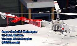
philosophies are present in this article. The "Super Susie" is powered by a Cox
.049 Tee Dee engine, has four channels, and weighs in at around 2 pounds. That is
pretty remarkable for early 1970s equipment. It's too bad someone doesn't produce
an .049-powered R/C copter today.
The Vintage RC Helicopter (VRCH.co.uk) website has color photos of the restored
Super Susie helicopter.
Designing RC Helicopters

Successful model helicopters can be small. Flying them takes
skill and much practice.
A "chopper" takes careful planning, testing, weighing, and performance prediction.
Determine flight capabilities by the chart, then start building.
John Burkham
Dieter Schluter, winner of the 1968 International RC Helicopter Competition in
Germany, has been writing articles on model radio control helicopters for Modell
(Ref. 1). And it's time someone did the same for an American magazine. In 1967,
two articles (Radio Control Modeler, Oct., Nov., Ref. 2) described the mechanical
aspects of full-scale helicopters. Several books, such as Gessow and Myers' Aerodynamics
of the Helicopter (Ref. 3), are standards on the subject.
The first three of Dieter Schluter's Modell articles describes the workings of
real helicopters, including the Bell and Lockheed stabilizing systems - which he
tried without success. The fourth discusses his experiments on a flight simulator
and how he succeeded in making a model of the Hughes 269A helicopter more stable.
Some typical calculations of model helicopter parameters, such as rotor disk
loading and power loading, and some hints based on full-scale helicopter practice
are presented in the fifth article. He gets ten pounds of thrust using a 60 engine
and the autorotation capability of a medium-size brick. A well-designed model helicopter
should give ten pounds of thrust from a .23 engine and have good auto rotation as
well.
The basic design approach for an RC helicopter is similar to that for a full-scale
helicopter or airplane. First, as a design guide, the general specifications, purpose,
type of configuration, approximate size and outstanding features of the model must
be determined. Next comes a rapid performance calculation for a better estimate
of size, performance and payload. Some sketching of the general arrangement of the
model can now be done. Tryout ideas on fuselage structure, transmission design,
landing gear method of attachment, and places for mounting the radio gear, with
servos arranged to connect directly and conveniently to the rotor and engine controls.
To complete preliminary design, estimate the weight and center of gravity of
all parts of the machine and then calculate the preliminary weight and CG of the
model. The CG should fall one-fourth to one-half inch ahead of the rotor shaft in
order to balance the air force due to rotor down wash striking the horizontal stabilizer
on the tail boom.
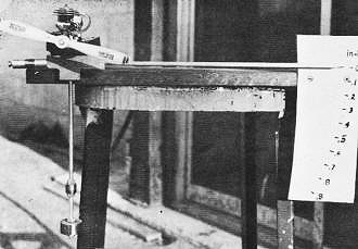
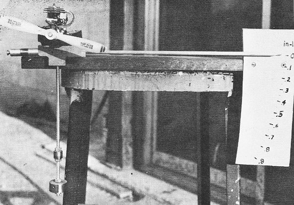
One must know at what speed the engine puts out its maximum horsepower
exactly as it will be used in the helicopter. This test rig gives relative power
output, rpm measured by strobe.
Next comes full-scale layout and detail design of the entire machine. Do some
stress analysis to make sure the blades won't fly off if the rotor is over-revved.
This stage is the meat of the helicopter design and requires a knowledge of mechanical
design, rotor dynamics, helicopter stability and control, and vibrations. On full-scale
aircraft, more exact aerodynamic performance analyses and complete stress, weight
and vibration analyses would be performed. The design then would be constantly changed
and improved until it met or exceeded the original specifications.
At this stage of model building, where utmost performance and safety are not
required, about all that need be done for the larger models (over five pounds) is
to recalculate the weight and CG position to make sure they are still within reason.
It also is worthwhile to check for ways of simplifying the design for ease and speed
of construction. Try to have someone else, even if he is not quite as knowledgeable,
look over drawings. A fresh approach can spot things overlooked through over-familiarity.
Construction now can begin and should be combined with testing assemblies as
soon as they are completed. Necessary changes then can be made immediately, obviously
saving time if these alterations affect other parts not yet made.
Flying is the most difficult and discouraging stage. Probable damages will need
repair. Changes and improvements to the design must be made to eliminate bugs which
did not show up in earlier testing. Acquiring the coordination of controls required
to fly even a good stable model helicopter will probably take longer than would
learning to fly a real helicopter. Long life and reliability must be built into
the model.
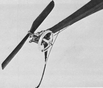
Cable drive turns the tail rotor with collective pitch control.
Preliminary Design
A detailed study of preliminary design begins with writing the specifications.
The purpose of the model might be one or several of the following: (1) to build,
with a minimum of construction and repair time, a small, simple trainer for learning
to fly; (2) to set records in endurance, speed, altitude or distance; (3) to compete
in RC scale events; (4) as an experiment to tryout a new rotor system or a new configuration
or any other special feature - a serious and valuable research tool; (5) to create
an aerobatic helicopter, flying crane, etc.
Most people begin with the trainer. At this stage in the development of the art,
the first one who can learn to fly a model helicopter then can proceed to set all
five world records with the same helicopter. Later, when competition develops, specially-designed
machines will be required to take the records.
At this point, the builder should eliminate conflicting requirements. For example,
it would be foolish to build a scale model for learning how to fly because that
means many crashes or hard landings. Scale means extra hours to build and to repair.
A .sensible compromise here would be to build a basic, compact machinery module
containing everything but the tail boom. For training purposes, a simple straight
tail boom and tail rotor can be added. For scale purposes, a scale tail boom can
be substituted, and the boxy fuselage rounded out with foam plastic slabs carved
to a scale exterior surface, then covered with fiberglass. Or, a fiberglass shell
could be made on a male or female mold and attached to the machinery module.
Once the purpose of the design has been determined, select the model's configuration.
The most common are: single main rotor and tail rotor, geared coaxial (one rotor
directly above the other), torque reactionless coaxial (or pinwheel) like most model
helicopters built in the last twenty or thirty years, side-by-side twin rotor, or
tandem rotor helicopter.
Most helicopters require some stability augmentation device. Flying an unstable
model helicopter by radio control is humanly impossible. The time an unstable model
takes to turn over is unbelievably short. Reaction time from eye to hand is around
two-tenth of a second. The reaction time of most RC servos is on the order of half
a second. Even without the servo time delay, a human pilot probably couldn't keep
up with the gyrations of an unstable model, let alone anticipate or lead its motion
by enough to damp out or quiet down an oscillation.
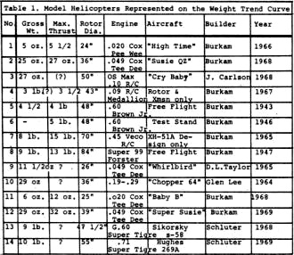
Data on weight/thrust, and engine displacement has been recorded since 1943.
Preliminary Sketches and Weight and Balance
Suffice it to say that all configurations, except single rotor, coaxial and pinwheel
are extremely difficult to stabilize. On coaxial helicopters, the controls are rather
difficult and complex. Pinwheels (the most common form of model helicopter) are
far and away the simplest to build because they have no transmission. They are easy
to stabilize with blade tip weights and servo tabs behind the blade tip. Other methods
of stabilizing single rotor helicopters, such as Bell, Hiller and Lockheed, will
work on pinwheels too. But they can't carry much weight for the power used. Ninety-five
percent of the engine power goes into that small prop turning at high speed, yet
it provides only about half the total lift. It would be interesting to see if a
large model powered by a .40 to .61 cu. in. engine could carry a full proportional
radio outfit.
Specifications usually include some indicator of size, such as "I want to build
the smallest helicopter that can comfortably carry a four-servo proportional radio
control outfit weighing 18 oz.," or perhaps, "I have this good .15 cu. in. RC engine.
I wonder how big a model it would power." Those ideas will be used in the next step,
preliminary performance estimation.
Before leaving specifications, a few niceties or good ideas should be kept in
mind while designing the model. Among them are: (1) Exhaust gases and oil shall
not spray over the model, but only on the gears. (2) All mechanisms, linkages, etc.,
must be easily accessible for repair, adjustment, replacement or modification. (3)
Room must be left to install a larger engine and/or larger fuel tank. (4) Provision
for autorotation of the helicopter in case of engine stoppage in flight is essential.
(5) No wood can be used for engine mounting or transmission structure because
of the effect on it of vibration and oil soaking. (6) Gears must be open and occasionally
lubricated or exhaust-lubricated, or gears shall be enclosed and oil- or grease-lubricated.
(7) Tail rotor shall be shaft- and gear-driven, or tail rotor shall be belt-driven.
Whatever the desired specifications, remember them during the designing.
The specifications used for the remainder of this article are as follows: (1)
trainer helicopter with four controls; (2) single main rotor and tail rotor configuration;
(3) as small and simple as possible and able to carry comfortably a quad proportional
weighing up to 20 oz.; (4) long-life two-stage gear reduction, open gears in first
stage, closed second stage; (5) shaft- and gear-driven tail rotor; (6) open, metal
machinery module; (7) engine up front, pointing forward with cooling fan/flywheel
and a spinner for easy electric starting, with exhaust spraying out to the side;
(8) wide skid landing gear; (9) provisions for future modification to permit autorotation;
(10) to be flown first as a free flight helicopter with throttle timer to partly
close throttle for descent (add RC gear later); (11) inherently stable as item ten
implies; (12) room for larger engine and/or fuel tank; (13) fuel capacity for 15
min. of hovering; (14) centrifugal clutch to allow starting without rotor turning.
In author's opinion, this arrangement of engine, rotor, and drive
train is simplest and suitable . However, it is untried.
Preliminary Performance Calculations
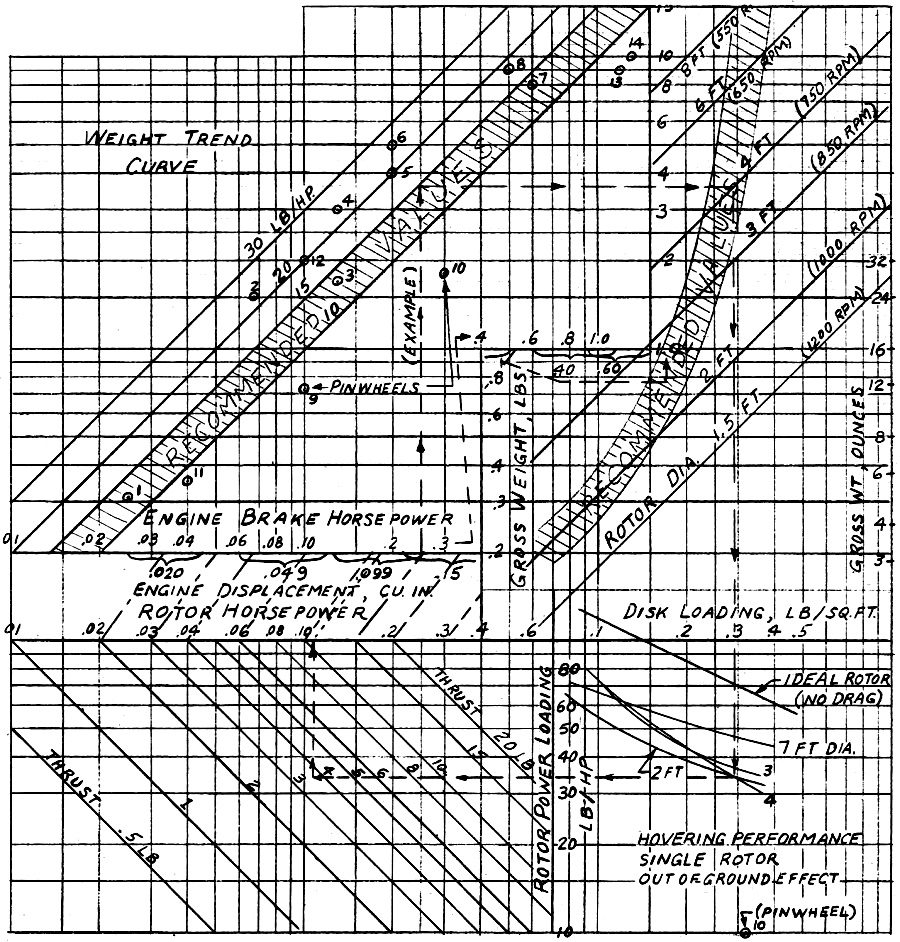
Now to use the handy chart (Fig. 1) which was first published in a paper given
at the 1969 DC/RC Technical Symposium (Ref. 4) This nomograph is really four charts
in one. The upper left chart relates engine brake horsepower, gross weight of model
and gross power loading and shows the trend of power loadings of a dozen or so previously
built (or designed) helicopters or rotors. Table 1 gives data on the fourteen examples.
The upper right chart is another arithmetic calculation relating model weight, rotor
diameter and disk loading.
The lower right chart gives actual test results of four different model helicopter
rotors in terms of rotor pounds per horsepower versus disk loading. This important
information is difficult to obtain any other way than by actual model rotor tests
at model rotor rpms. The effect of these very low Reynolds numbers on drag makes
model rotor performance prediction based on full-scale helicopter rotor performance
most unreliable and optimistic. Theoretically, these curves should not cross. The
reason they do cross is because all tests were done on different test stands at
different times using rotors with different airfoils, different twist and taper
and different surface finishes.
The bottom left chart is just an-other arithmetic calculation to find rotor horsepower
from rotor power loading and rotor thrust. Logarithmic scales were used so that
the lower end of each scale would be spread out a little and the upper ends would
not be spread out so far.
The usual approach to sizing a helicopter is to take the desired engine and estimate
its maximum brake horsepower and its rpm at peak output. Peter Chinn's excellent
engine review articles in Model Airplane News and the two British magazines, AeroModeller
and Radio Control Models and Electronics, are the handiest source of engine data.
The surest method of getting engine performance is to calculate it with a rig as
shown in Fig. 2. It uses a Vibratach, a Heathkit Thumb Tach, a stroboscope, or even
a pitch pipe, to measure rpm.
Having the horsepower, start at that point on the engine bhp scale and go straight
up in the upper left chart to somewhere in the shaded band of practical values.
For a first cut, 15 lb./hp is a safe bet. It is just a question of how light a helicopter
can be built for the size of engine chosen, using a practical size rotor given in
the upper right corner.
This chart relates only to gear-driven single rotor helicopters
and is for .01 to .20 engines. Extrapolate for higher values.
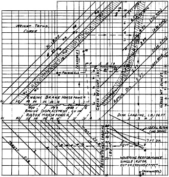
Chart for Quick Calculation of Helicopter Size From Given Engine
Size.
Start with engine horsepower. Go up to chosen power loading.
Go right to chosen rotor diameter, down to same rotor diameter, then left to chosen
thrust (or gross weight). Go up to rotor horsepower then diagonally up to
engine power, if you come out to the left of where you started it should get off
the ground.
A smaller diameter rotor and a smaller overall helicopter for a given size engine
would result in lower power loading, as most of the German model helicopter builders
have done (Ref. 5).But then the disk loading will be so high that the model descends
too fast in autorotation. Similarly, a lighter disk loading than shown in the shaded
area of the upper right corner graph might be chosen in hopes of improving hovering
performance. But it won't do any good if the model could not be built that light.
For the chosen example, a dotted line is drawn on the chart (Fig. 1). Starting
with engine, the Medallion 15 RC puts out about .25 hp at 14,000 rpm. Going up.
along the .25 hp line to the diagonal 15 lb./hp line gives 3.6 lb. gross weight.
Continue to the right, along the 3.6-lb. line to the diagonal 4-ft. rotor diameter
line in the upper right corner, then straight down to the disk-loading scale, which
gives .29 lb./sq. ft. Going on down to the 4-ft. rotor curve, then left to rotor
power loading gives 34 lb./hp. Keep on to the left to a point between 3- and 4-lb.
thrust (3.6) and go up to rotor horsepower, reading .11. Then up diagonally parallel
to the line connecting rotor hp with engine bhp, and read .18 bhp. (This last step
is equivalent to dividing rotor horsepower by 0.6 to get engine power, which allows
a generous 40% loss of power in transmission, cooling and tail rotor.) This .16
hp is well below the .25 bhp of the Medallion 15 RC.
An O.S. Max III 15 RC, giving .29 bhp, would have been a better choice, but the
Medallion was on hand, is American-made, and is easy to clamp around the front end
of the crankcase. Should power be needed for some future altitude record attempt,
a Cox Special 15 MK II can be dropped in with the Medallion or other type throttle
clamped around the cylinder. That would put out up to .5 hp. So would a Supertigre
15 with a throttling carburetor added.
Suppose a 4-ft. rotor, 15-powered helicopter can't be built as light as 3.6 lb.
or suppose some streamlining, beautifying foam plastic is to be added to the model.
How heavy can it be and still take off? Start over again at .25 engine bhp, go up
to 4 1/2 lb., right to 4-ft. diameter, down to .37 lb./sq. ft., on down to 4-ft.
rotor curve, left to 30 lb./hp, farther left to 4-1/2 lb. thrust, up to .14 rotor
hp. Then going up diagonally to engine horsepower, the line comes out to .24 hp.,
just about where it started. This theoretical model should still be able to struggle
off the ground. Had the estimate been too high for maximum gross weight, the end
result would have been too high an engine hp. With a Max III 15 RC without muffler,
the model could have gone up to 6 lb. and still gotten off the ground.
For those who want to size the helicopter to a radio outfit weighing a specific
number of ounces, use the rule that a good helicopter has a maximum thrust of about
twice its empty weight (minus radio gear and fuel). Not all flight is at maximum
thrust, but perhaps at 3/4 of maximum thrust. This means that gross weight (flying
weight) should be 3/4 of maximum thrust or 1 1/2 times empty weight. If the gross
weight is 1 1/2 times the empty weight, then the difference (useful load) is 1/2
the empty weight or 1/3 the gross weight. Thus, gross weight is three times the
weight of radio plus fuel. Start from this point, gross weight, on the top half
of the chart, work backward to find engine bhp and forward to find rotor hp required,
making changes in rotor diameter until rotor horsepower is less than .6 of engine
bhp.
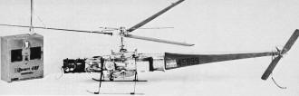
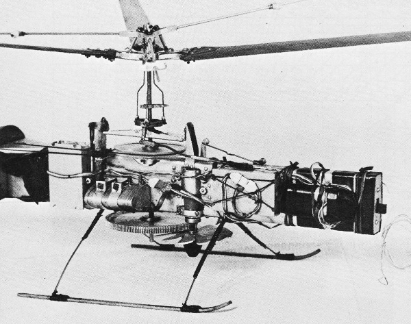
Meet Super Susie. Using a Tee Dee 049 and four-channel radio,
she has flown successfully quite often, and even held a world's record.
This chart assumes a well-proportioned rotor and a fairly efficient transmission
and cooling system. The rotor should have a solidity (ratio of blade area to rotor
disk area) of about .05 to .07. The blades should be carved to a nice airfoil shape
such as the Clark Y, NACA 23012, NACA 8-H-12 or other flat-bottom airfoil. Symmetrical
section NACA 0012 is good for controllability but it is about three or four percent
less efficient than the ones with cambered mean line. Those with undercamber would
be even more efficient than the flat-bottomed ones but their high moment coefficient
(tendency for the section to pitch down) would probably cause the blades to flutter
or diverge at flight rpm. Taper and twist of the blades five or six degrees of washout
at the tip) will also improve performance by about five percent but are a little
more difficult to carve into the blades. The better the surface finish of the blade,
the better the performance.
Rotor rpm should be about as noted on the diagonal lines for different rotor
diameters in the upper right chart, and blade angles measured from the plane of
the rotor to the flat bottom of the airfoil should be eight to ten degrees. Tests
and calculations show that running the rotor more slowly and using higher blade
angle would give more thrust per horsepower. But the coning angle would be excessive
and the blades would be operating nearer stall. If the model goes forward very fast,
the retreating blades will stall (those blades whose tips are going toward the rear).
Stalled blades mean rough running, vibrations, and short life of the rotor system.
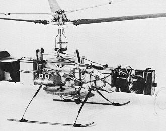
As author emphasizes, efficiency, not brute power, produces flyable
helicopters. First build something small and easily repaired.
Some idea of possible arrangements of engine, transmission, radio gear, cooling
fan, fuel tank and landing gear is needed to begin laying out the design. Some desirable
attributes of a well-designed helicopter are as follows:
(1) Engine-transmission-rotor shaft should be a compact, rigid unit for accurate
and enduring gear alignment and minimum structural weight.
(2) Disposable weight, especially if it is a large percentage of empty weight,
such as oversize fuel tanks, should be located near the rotor shaft and CG for minimum
change in CG.
(3) Radio gear should be well protected from exhaust fumes. A hovering helicopter
tends to recirculate the air, especially in a confined place (closed garage).
(4) Tail rotor diameter should be one-fourth to one-fifth of main rotor diameter
and tail rotor rpm should be, respectively, four to five times main rotor rpm.
Several possible arrangements follow: (1) The engine could be pointed down, with
a one- or two-stage spur gear reduction to the bottom end of the rotor shaft. That
usually puts the needle valve below the fuel tank, and fuel drips out after filling
the tank, but before starting the engine, unless the model is held in a tank-low
position. A two-stage gear reduction would make the rotor turn clockwise viewed
from above (left-handed). The only disadvantage of a left-hand rotor is that, when
testing it in an electric drill, the drill has to be reversed or the rotor turned
upside down.
Self-engaging, rather than centrifugal, clutch allows autorotation.
Sufficient blade area is provided for a safe power-off landing.
(2) The engine can be pointed up, then a two-stage gear reduction would give
a right-hand rotor, a needle valve above the fuel tank, and the prop shaft on top
for convenient starting by electric starter. This means a clutch is needed between
the motor and rotor so the engine can be started without starting the rotor. A fan
on the prop shaft would blow cooling air down and would not be likely to blow exhaust
drippings up onto the rotor blades.
(3) In another arrangement the engine points to one side. A spur gear reduction
to another shaft running crosswise, then a 45-degree helical gear on that shaft
driving a helical gear of larger diameter on the main rotor shaft, is a nice compact
transmission. The engine, sticking out the side, can be started with or without
a clutch. The cooling fan would blow crosswise, taking exhaust goop out the side.
(Muffler or exhaust pipe is needed here to turn the exhaust 90 degrees.) The fan
thrust should be opposed to tail rotor side thrust to reduce sidewise drift when
taking off. The needle valve easily could be on a level with the middle of the fuel
tank. When choosing an arrangement, make free-hand sketches and see how the design
develops, including the complexity of structure needed to hold it together.
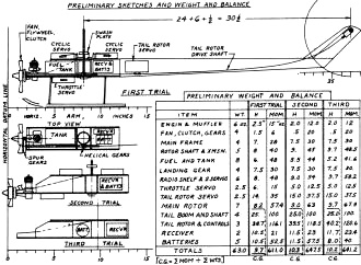
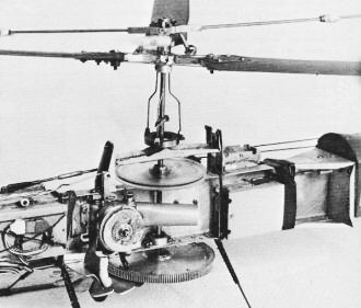
(4) The arrangement chosen for further discussion is shown on the chart: Preliminary
Sketches and Weight and Balance. The engine sits in front of a piece of sheet metal
bent up into a square U shape. The prop shaft, pointing forward, holds a small spur
gear, a centrifugal clutch, a fan/flywheel and a spinner for starting by electric
motor. The spur gear drives a larger gear out to the left side on an intermediate
shaft running back just inside the U-shaped frame past the fuel tank to the main
rotor transmission. There, 45-degree helical gears perform the right-angle drive
to rotor shaft and give a further speed reduction. Bulkheads in the U channel, and
a cover plate on top, serve to enclose the rotor transmission, allowing it to be
partly oil-filled for lubrication. The intermediate shaft comes out the rear of
the rotor transmission and is connected to a piece of 1/16" music wire drive shaft
to the tail rotor.
The two main rotor control servos mount on a plywood platform over the fuel tank
and transmission. The throttle servo and connection to main rotor collective pitch
are underneath the channel below the fuel tank. The landing gear attaches to the
bottom of the channel. The tail rotor servo is mounted in the forward end of the
tail boom so that when the latter is removed the servo can merely be unplugged.
The aft end of the tail boom turns up to get the tail rotor higher off the ground
for operation in grass and for flared landings. The upturned boom end is made wide
enough to add fin area for better directional stability. The flexible shaft drive
turns this corner without difficulty inside a nylon guide tube.
The preliminary weight and balance estimate is not difficult. Merely list various
parts of the helicopter in convenient groups. Estimate the weight of each group
and write it down. This is largely common sense guesswork, perhaps aided by actually
weighing a few items-such as a piece of shafting or pine wood the size of a blade
or a piece of music wire for landing gear. Estimating the CG of each group by eye
is easy. Then measure the distance of each group CG from the datum line up front
and write that down under H arm. Multiply each weight by its H arm to get moment.
Add up the moments, divide by the total weight to get the aircraft CG. In this case,
the first trial put the CG at 9.7 in., whereas the rotor shaft was at 8.2 in. That's
bad.
Two trials later, after moving batteries forward and rotor transmission aft,
the CG came to 10.2 and the rotor was at 9.7. The transmission will be moved aft
a little in the full-scale layout to bring the aircraft CG slightly ahead of the
rotor shaft.
Undoubtedly this will not be the final arrangement but is only a reference point.
If something is moved aft, something else must go forward to preserve an approximate
balance. After the model is finished, the batteries probably will have to be shifted
else-where to achieve proper balance.
Next step in the design is a full-scale layout and solving design problems. The
choice of rotor and stabilizing system can be left until later. Hopefully an idea
for that ideal stability or control system may develop as a result of experimentation.
References
(1) Schluter, D., "Model-Hubschrauber-Technik," a series of articles, Modell,
Jan., Feb., Mar., Apr., May, 1969.
(2) Andrews, J., "Helicopter Aerodynamics," Parts I and II, Radio Control Modeler,
Oct., Nov., 1967.
(3) Gessow, A., and Myers, G.C., Aerodynamics of the Helicopter, Frederick Ungar
Publishing Co., New York, N.Y.
(4) Burkam, J. E., "A Radio Controlled Helicopter," paper presented at the DC/RC
Symposium, May 1969.
(5) Burkam, J. E., "First International R/C Helicopter Competition," Model Airplane
News, April 1969.
Posted January 29, 2024
(updated from original
post on 9/16/2017)
|