|
The U.S. Army Air Corps' BC−1
low-wing monoplane was North American Aviation's first trainer aircraft (company
designation was
NA−16). The "BC" part of the designation stands for "Basic Combat," so the
Army intended to use the BC−1 on missions. If you think it looks a lot like the
AT−6 Texan trainer, it is
because the AT−6 evolved from the NA−16. In fact, the Wikipedia entries give
April 1, 1935 as the date of maiden flight for both of them. 17,000 variations were built from 1935
through 1939. This construction article and plans appeared in the May 1941 issue
of Flying Aces
magazine. Wingspan is about 20", making it a rather small model. Standard stick
and tissue methods are used, and a pattern is provided for carving your own
propeller. Send me an e-mail if you need full resolution scans of the plans.
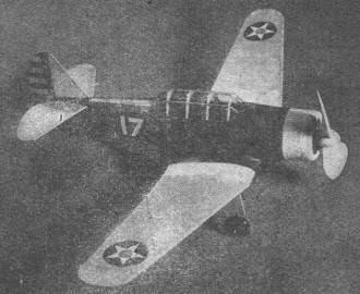
Follow these plans and instructions for building one of the most
realistic scale models ever designed to fly.
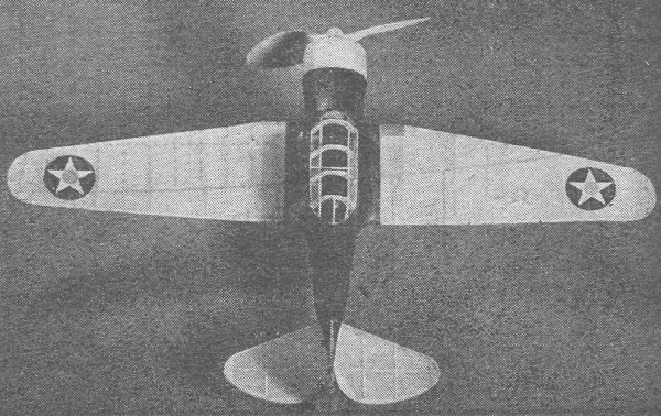
A perfect example of craftsmanship. It flies as well as it looks.
by Milton Kahn
Devotees of flying scale jobs haven't a very wide selection these days since
most of our planes are either mid-wingers or low-wingers. On top of that, the majority
are military types.
Some sort of a bugaboo still exists, however, that low-wing flying scales are
not so hot, and as a result are more or less treated like a stepchild. Nonsense!
That's all this author has been building and flying for the last three years, and
he can report nothing but excellent flights with swell flying characteristics to
boot - including this month's job.
The North American trainer in Air Corps circles is known as the BC-1 basic combat.
The manufacturer's designation is NA-16-3. This two-place ship is widely used in
preparing Flying Cadets to eventually handle swift, single-seat fighters. This "prep
school" ship is a tricky job, and has to be flown every minute. The BC-1 is powered
with a 550-h.p. Pratt & Whitney Wasp engine and cruises at 195 m.p.h. It has
a maximum speed of 210 and a rate of climb of 1500 feet per minute. Landing speed
with flaps is 67 m.p.h. and cruising range is 900 miles. Structure is all-metal
throughout and tail surfaces are stressed-skin covered while moving parts are fabric
faced.
Fuselage Construction
Easiest way to start things right is to remove Plates 1 and 2 from the magazine
and pin down to a flat surface. Over these pages, spread a convenient sized sheet
of wax paper. The necessity of this will be obvious. Your first step is to cut to
correct size the four longerons and pin them into position on the side view. The
longerons are identified by the dotted longitudinal lines.
Cement the uprights (also called compression members) in position. After one
frame is completed, lay down the second side and in due time remove so that both
sides can be attached by cross braces. The cross members are cemented at right angles
to each upright. An illustration is best given on Plate 1 showing a front view of
the frame with formers around it.
Crack the frame slightly at the point where former F-3 is to be mounted. Taper
the nose so that F-1 can be cemented as shown in the top view. The remaining three
formers (also parts of F-1) required to round off the nose is shown in full size
front view on Plate 1. The side formers are notched for a single side stringer,
top and bottom formers, for three stringers.
Formers, F-4 to -7 inclusive, are cemented as shown, while on the bottom, formers
F-8 and 9 (formers and wing spars combined) to F-13 are cemented in position. Later,
F-2 formers are attached on each side of the body. After this is secured, fit in
the 1/16" by 3/32" stringer as shown and taper as noted on Plate 2. Up front, this
stringer is cracked slightly and cemented at the angle shown between the nose bulkhead
and F-2.
Wing fillet parts WF-1, of which two are required, are cut to shape and attached
after the leading edges of the stub wing are cemented into position. Rear wing fillet
WF-2 is likewise attached when ready.
The cockpit hatch is strengthened by cementing in the stringers where required.
The curved rear part of the stringers are cut to the necessary shape from 1/16"
sheet. Stringers required for the top and bottom formers are attached next. Omit
the center stringer for the bottom formers until the entire wing has been built
and cemented in position. Study your plans so that this is made entirely clear to
you before covering the model.
Wing and Tail

Sturdy construction throughout enables the craft to stand up
well.
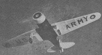
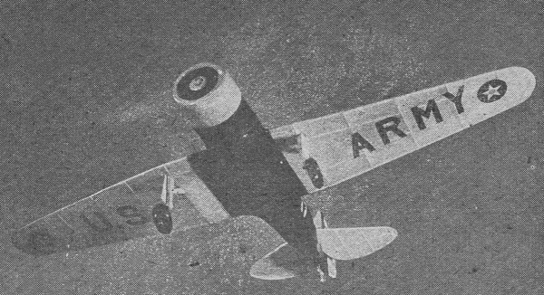
Graceful lines and beauty of flight are captured by this excellent
take-off shot.
Before making right and left wing panels, the center section or stub wing, must
be built into the fuselage. Since formers F-8 and -9 are already cemented in place,
attach wing ribs R-1 and 2 into the notches provided for them. Next fit into their
leading edge slots, the leading spar. The trailing edge spar is tapered as required
and also glued. Curved sections forming fillets WF-1 and -2 are next to be cemented.
Wing construction is conventional and simple. Shape the designated ribs and cut
the notches out carefully. Pin down the wing spars directly over the wax paper covered
plans and cement each rib as noted. Add the leading edge spar, followed by the trailing
spar which should be tapered to conform correctly. The tips are added on last. Cement
all joints well and later sand down the rough spots. The second half of the wing
may be made by reversing the plan. Beforehand, however, go over the outlines with
a pencil so that the impression shows clearly through the reverse side.
Ribs, spars, and leading edge of both the rudder and elevator are cut to correct
lengths from 1/16" sq. hard balsa. The curved edges are trimmed to shape from 1/16"
sheet. Apply cement liberally on all the connecting parts.
The rear hook is shaped from No. 12 piano wire, inserted into the tail post as
shown, and bent to shape and cemented. The tail wheel fork is made likewise and
cemented securely. At is time, metal fittings for the landing gear and prop shaft
may be shaped from wire of the same gauge.
Cowling and Landing Gear
The front edge of the cowling is sanded to shape from a disc of required proportions.
Use a compass to obtain the correct diameter and trim with a sharp razor. Make an
opening in dead center for the removable nose plug. A slight recess is sanded in
about 1/16" deep as indicated by the dotted lines in the side view of the cowling.
To attach the frontispiece of the cowling, first lay it flat on its face. Then
cement four pieces of balsa each measuring 1/8" by 1/8" by 11/16" upright at quarterly
intervals. After they have hardened in this position, take the whole unit, and cement
it flush against the open-faced nose. When this dries, the cowling sides are covered
with 1/32" sheet. However, first round off the 1/8" square mounts with sanding.
Use model-making pins to aid in holding the sheet covering until the cement hardens
sufficiently to warrant their removal.
The landing gear legs are made from hard balsa dowels a single length and then
sanded and cut to shape. The front view plan of this unit is shown on Plate 1. After
the leg is shaped, take a perfectly straight length of wire and carefully insert
it through dead center of the strut all the way down until enough of it comes through
the bottom to be bent outward for the axle. Apply a dab of cement on top and bottom
ends.
The outer flaps are cut to the required pattern from 1/6". sheet. This is shown
in full size on Plate 1. Flatten the outer side of the upper part of the landing
strut slightly so that when the flap is cemented it may adhere more easily.
When both landing gear legs are ready, attach them with a liberal amount of cement
as indicated by the positions shown in top and side views.
Propeller and Covering
Cover the propeller from a hard balsa block measuring 1" by 1-1/2" by 7". By
using slightly larger wheels the diameter may be increased. Enlarge the pattern
shown on Plate 3 in order to obtain the full size blade. The spinner cap is carved
integral with the prop. Cup the inner sides of the blades for greater efficiency.
Insert the wire shaft as required, slip through the nose plug and bend to shape.
Balance the blades perfectly.
Covering the ship must be done in an expert manner in order to bring out the
best looks for this craft.
Start with the tail parts. Use yellow Japanese tissue as in this case it is the
standard color for a military plane. Apply the dope lightly along the leading edge
of the elevator from one end to the other. Lay on the paper and smooth out the wrinkles.
When the liquid dries, apply the dope more generously to the ribs, center spar and
trailing edge. Fold the paper over these parts and pull tightly.
The outer edges are then trimmed leaving a 1/8" margin. This is doped and folded
in all around the edges. The uncovered side is heated likewise and trimmed. The
rudder is covered with yellow tissue and after this is completed, both surfaces
are sprayed lightly with water and set aside to dry. These surfaces must not be
doped with banana liquid as they will warp completely out of shape.
The wing panels are also covered with yellow tissue. First cut out a pattern
of the outlines, leaving a quarter inch margin all around. Apply the dope over the
front edges of the ribs and flatten the paper to them. As soon as the liquid dries,
extend applications of dope down to the trailing edges and smooth the paper right
over it. Then the leading and trailing edges are tacked down and the tips trimmed.
The top part of the wing is covered in the same manner.
When both panels are completed, shrink the tissue by water spraying both sides
of each wing. After that, apply at least two coats of dope. Regulation colored stars
are attached to the top and bottom surfaces as shown in the wing plan view on Plate
3. The letters spelling out U. S. ARMY should be trimmed out of black paper and
mounted in the correct manner. The flight photograph illustrates this best.
Before covering the fuselage, install the rubber power and hook on the washers
and propeller.
The fuselage is covered in sections. First the sides, then the rounded top, and
lastly the bottom. Blue paper is used throughout for the body, including the fillet
section extending from the side of the body out to the first rib of the stub wing.
The space between that rib and the outer rib of the stub is covered with yellow
paper. The cowling may be covered with blue paper if desired. It may, however, require
more than one covering in order to darken the lighter colored sheet balsa.
The cockpit hatch is covered with either isinglass or thin sheet celluloid. Trim
the rudder with regulation red, white, and blue stripes. A sheet of such tri-colors
may be purchased at any model supply shop.
Assembly and Flying
Attach the wing panels to the stubs with plenty of cement. Place object at the
extreme tips of the wings so that the dihedral angle measuring 1-1/4" will be obtained.
Insert small model-making pins between the first wing rib and the stub wing rib
to aid in holding this angle. Later remove the pins and fill up the holes with small
dabs of cement.
The stabilizer is slipped into position and cemented fast. The rudder is mounted
next. Be sure that these surfaces line up at right angles to one another.
As the ship stands, it is a bit tail heavy and therefore requires additional
weight to the nose. This can be accomplished by adding five or six coats of dope
to the cowling, and after they are dry dab another several coats of blue dope. Paint
the landing gear flaps blue. Coat the propeller several times, and if slightly more
weight is needed, use the inner trough of the cowling to accommodate small pieces
of lead, solder, etc.
Trim the model by balancing it on your fingers. The balancing point should be
right in front of the last.
The ship shown in the photographs is equipped with celluloid wheels. These are
a bit hard and noisy. A pair of balloon tired wheels of the same diameter may be
purchased at any model shop. It is suggested that this kind may be substituted for
hard wheels as they make for easier landings. Glide the ship until the best is brought
out. Then follow up with minor power flights. Study its behavior and make any adjustments
that are required.
For real flights, use a geared winder and stretch out the strands at least twice
their length. Try take-off flights. They're really very fascinating to watch.
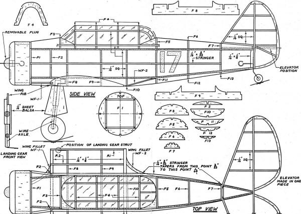
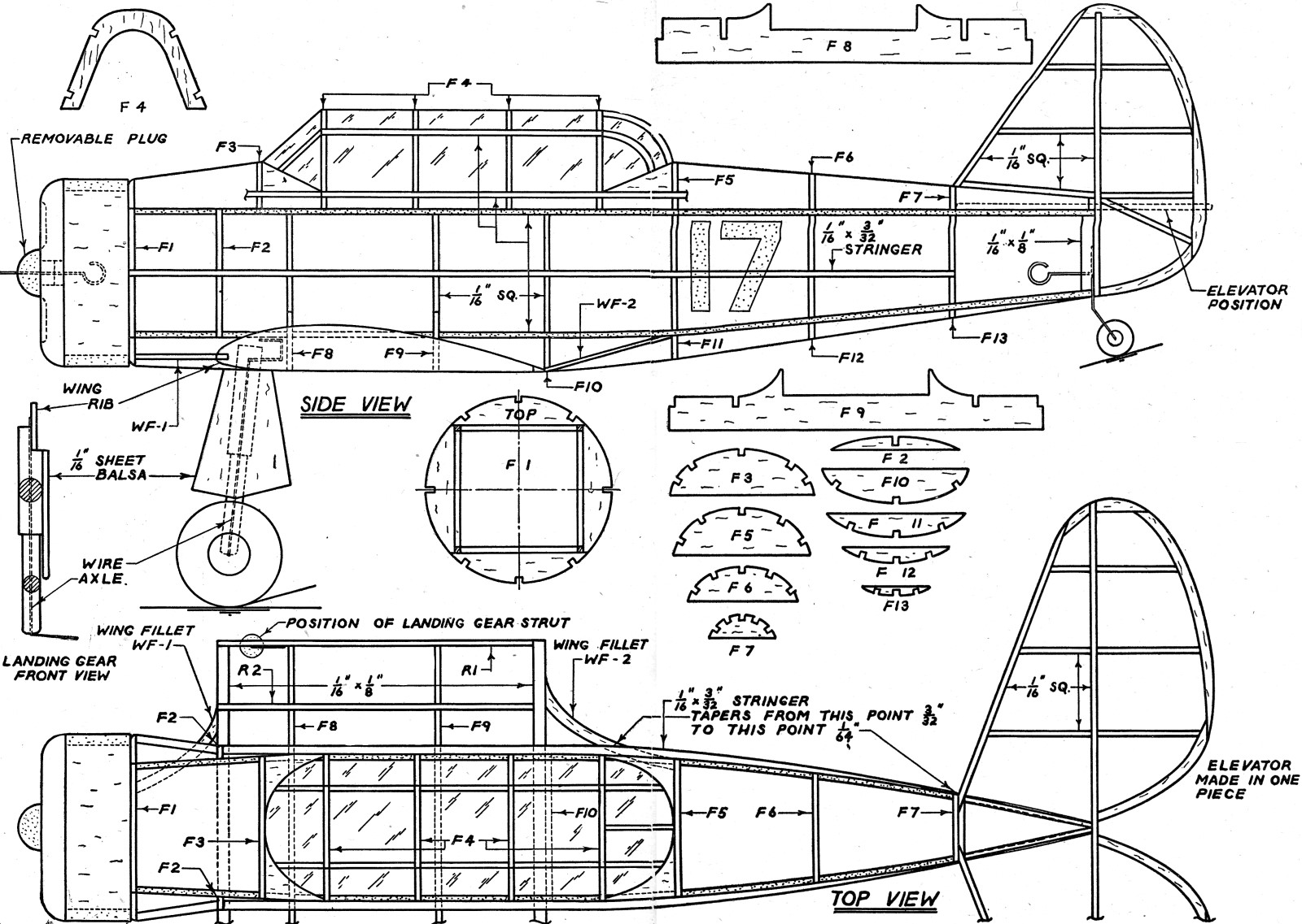
Army BC-1 Fuselage Plans
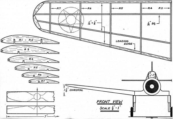
Army BC-1 Wing Plans
Posted March 7, 2020
|