|
In 1941, model airplane engines invariably were gasoline-driven
ignition systems. As such, onboard batteries were required to light
the spark plug. If you are relatively new to the aeromodeling hobby,
then when you think of an airborne battery, you likely envision
NiCad, NiMH, or Li-Po cells that are relatively compact, lightweight,
and trouble-free. Back in the day, though it could mean anything
from a few carbon cells to a lead-acid storage battery. Early days
of radio control flight routinely had lead-acid batteries to provide
the power needed to run vacuum tube receivers and electromagnetic
actuators. In the case of the Guppie, a 20-second motor run rule
for its competition class allowed a smaller cache of cells to be
carried. Its 6-foot wingspan and classic construction would make
the Guppie a great vintage conversion project using an electric
propulsion systems and R/C.
Build this Swell "Guppie" Gas Job
Because of her profile resemblance to the famed fishbowl pet,
they call her "Guppie." That's not just a name - it's the secret
of her success! Try your hand at this unusual flyer and see for
yourself.
By Martin Powell
Author of "Try This Orbit Gas Buggy."
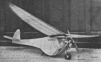
An outstanding feature of this fine flyer is
its deep belly. Additional side area presented by the odd shaped
fuselage prevents the ship from going into the dreaded spiral "coupe
de grace."
Because model builders persist in flying their gas jobs in any
kind of weather, the tendency prevails to build rugged ships, despite
added weight. It's quite a thrill to watch your gassy battle inclement
weather and yet have the assurance that a hot landing won't result
in its winding up like a ball of wool. But how about that same ship
sent aloft on a calm day? The added weight displays itself with
telling effect. Its glide would probably resemble the descending
angle of an express elevator during the rush hour - straight down,
full car!
Probably after witnessing such a performance, you desired to
build a gas job which would combine a light but rugged structure
and at the same time possess gliding characteristics that almost
defy Newton's law. Well, fellow modelers, meet the "Guppie." With
due modesty, the author claims this is the ship that almost does
the defying!
Among the many features of this unique craft is its deep belly.
During a sideslip the model will actually fly on the area presented
by the odd shaped body and thus prevent the dreaded spiral dive
which invariably ends up you know where. Also, the deep belly enables
the model to take-off in flying position, thereby shortening the
take-off run immeasurably. Now that we must fly on the 20 second
motor run rule, the importance of the foregoing cannot be underestimated
in the least.
The "Guppie" has been designed to operate with either 1/5 or
1/6 h.p. engines. For accuracy in construction and alignment, enlarge
the plans for each part in full scale and work out such sections
on a table or board.
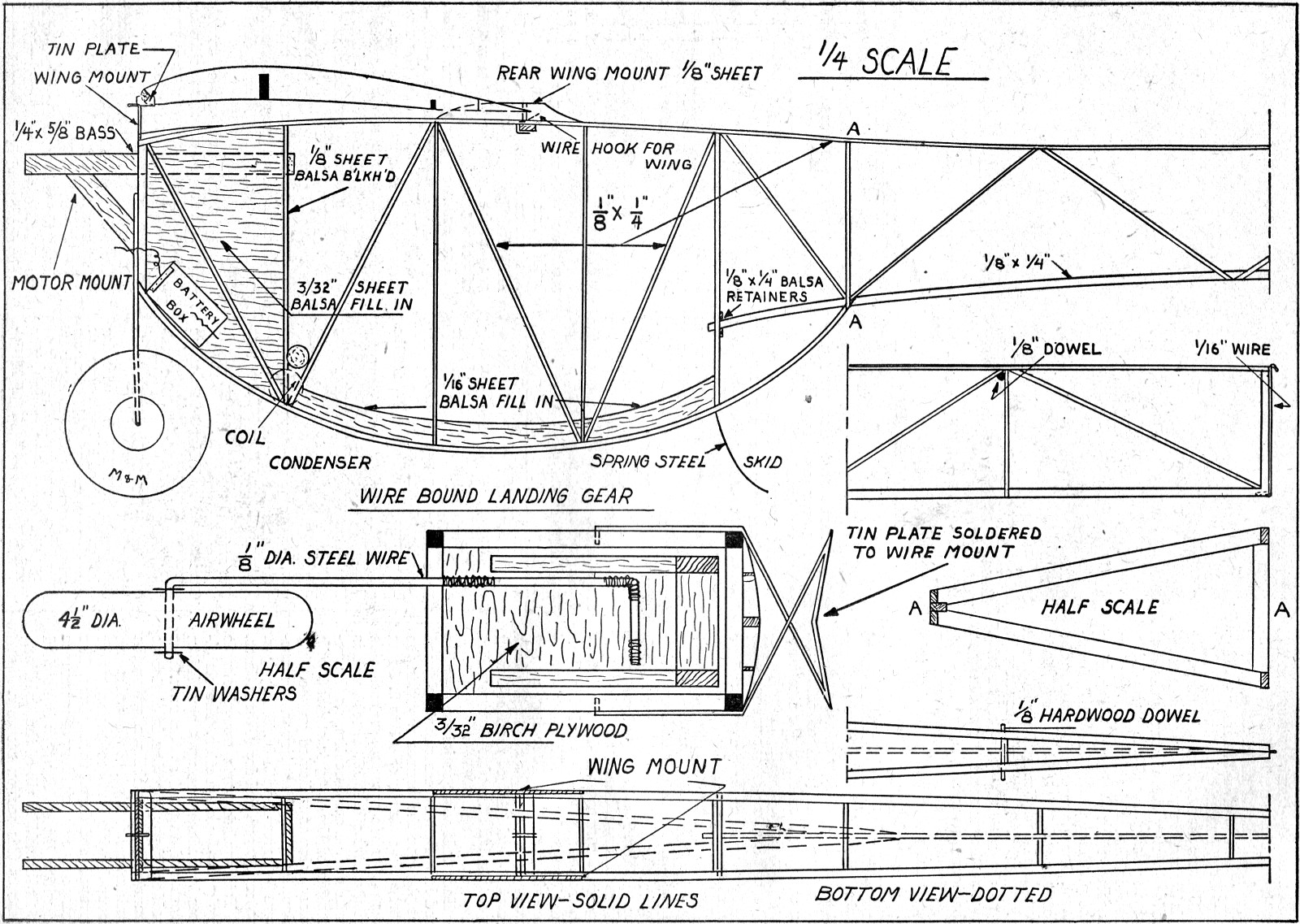
Fuselage and Wing Mount
The fuselage structure is rather unusual, inasmuch as its cross
section changes from rectangular at the firewall to triangular at
section "A-A" and from that point out.
Two fuselage sides are built by pinning down longerons for the
upper and lower portion. The lower longeron is cut off at section
"A-A" while the top longeron extends to the extreme end. Upright
and diagonal members are cemented in place from the firewall to
section "A-A." To assemble, cement the tops of the longerons together
at the rear end also at section "A-A" on the bottom. When thoroughly
dried, the firewall, cross pieces, and fuselage bulkhead are cemented
as indicated on Plate 1.
A third longeron, which forms the triangle section, is cemented
at section "A-A" and held in place by the uprights and diagonals.
Two cross piece retainers cemented above and below the longeron
are shown in their respective position on Plate 1. Cement all joints
generously and allow plenty of time to harden.
The metal wing mount is bent to shape from 1/16" dia. music wire
to the design shown in the front view drawing on Plate 1. The perspective
view on Plate 4 shows how a tin plate is placed upon the wire frame
mount and soldered. Imbed the wire prongs of the mount into the
fuselage sides as shown in the front view and cement securely.
Motor Mount and Landing Gear
The motor mount is of the simple beam-type, extending through
the firewall and the balsa bulkhead directly behind it. Angular
supports for the mounts are cemented to the underside of the beams
- not nailed. Use cement generously around all the joining parts.
The rear wing mounts are shaped from sheet balsa and are cemented
to the top longerons, as shown on Plate 1. A cross piece extending
between the undersides of the top longeron holds the rear wing hook,
which is shaped from 1/16" wire. A single former made up in three
sections is cemented directly over the firewall. Its stringers gradually
diminish and are glued flush to the first cross piece directly behind
the firewall. The sheet balsa fill-in is made up of sections fitted
flush between the uprights and diagonals.
Music wire of 1/8" diameter forms the single wheel landing gear
support. The design in the front view drawing on Plate 1 shows how
securely it may be bound to the firewall with either soft copper
wire or strong thread. Tiny holes bored at intervals in the firewall
allow the thread or wire to pass through and thus hold the landing
gear with great strength. Cover the entire portion with cement and
allow several hours to dry. The rear skid is shaped into a hook
from spring steel inserted upward into the lower longeron and cemented
in that position permanently. The skid, in the position just described,
heightens the angle of the take-off which thereby shortens the run.
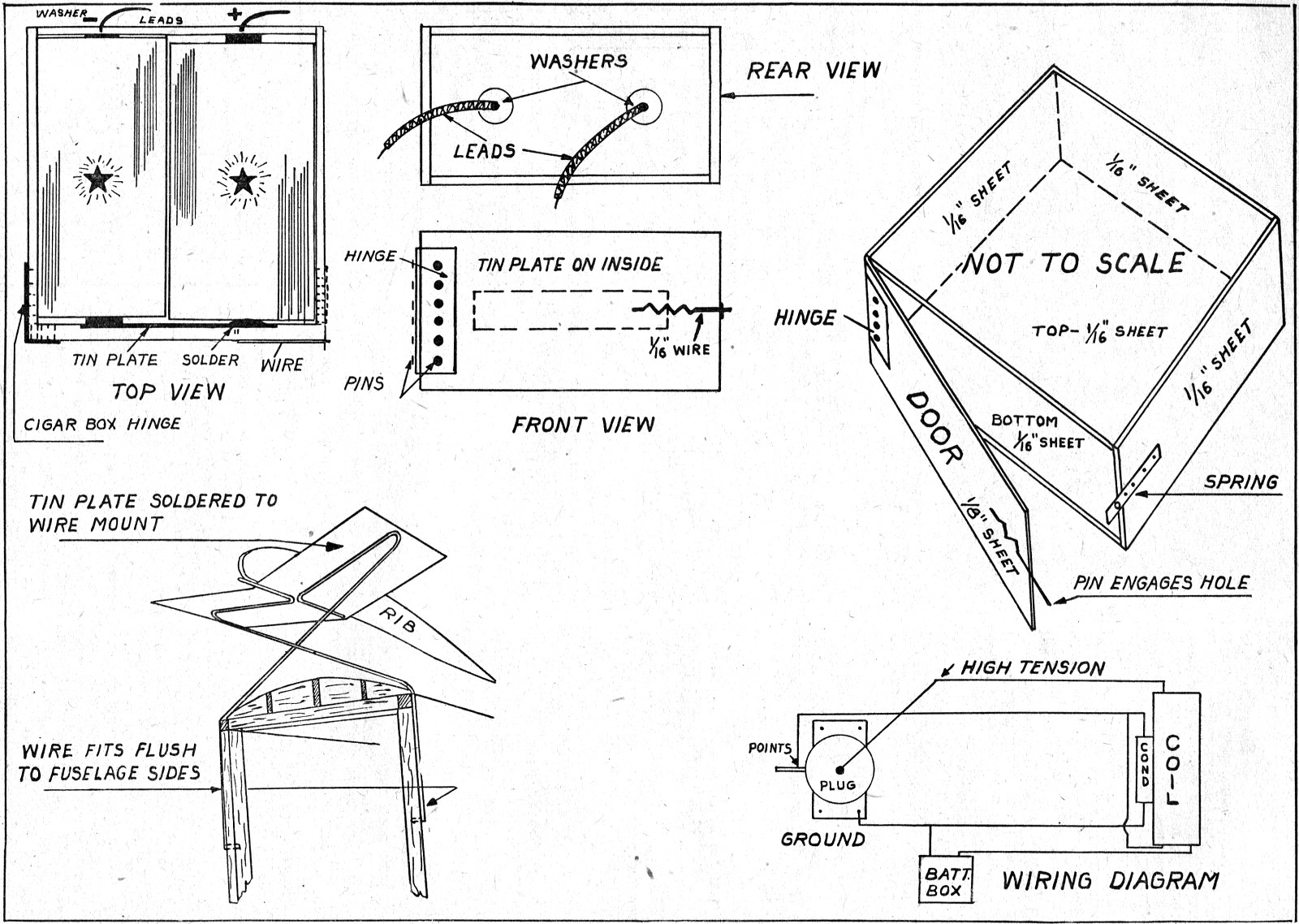
Battery Compartment
The battery box is made from the drawings shown in full scale
on Plate 4. The unit is composed entirely of balsa. Be sure that
when the batteries are inserted they make full contact at all times.
Cement the box to a 1/8" balsa sheet platform. The portion of
the underside of the fuselage between the rear of the firewall and
the balsa bulkhead is filled with this slab. This piece is mounted
on pin hinges which allow the platform to flap open and downward.
The hinges are situated at the forward end. After the battery box
is completed with the ignition leads extending through holes in
the firewall, coat the underside of the box with plenty of cement
and press firmly to the door-platform.
When the cement dries and the platform is swung up and locked
into position, the effect will be exactly as shown in the side view
of the fuselage drawing on Plate 1. A sheet of balsa fill-in of
3/32" thickness is cemented on both sides of the fuselage as shown.
This provides additional strength and takes up the stress exerted
by the torque of the propeller. The coil and condenser are mounted
with any type of wire fittings to hold them securely.
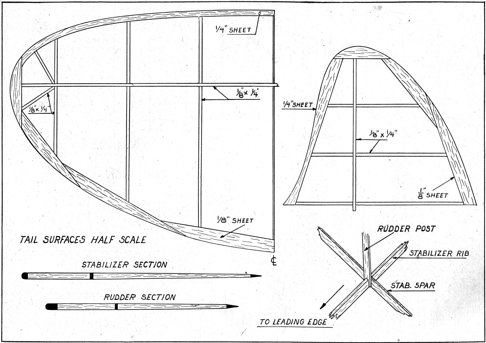
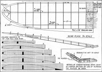
Wing and Tails
Careful plotting and trimming of the ribs assures a balanced wing.
The leading edge is made by inserting a hard balsa strip, 1/4" sq.,
in the notches and cemented at the required angle. Later, it is
rounded off to conform with the shape of the airfoil section. The
wing tips are made up in a series of parts which must fit flush.
Aft of the No.1 wing spar the trailing edge is tapered as shown.
Each half wing is joined together and held fast by cementing
plywood tie plates in the manner shown in the perspective sketch
on Plate 2. From the center rib outward, on each side of the next
rib, 1/16" sheet balsa is cemented. A small section on the underside
of the wing is covered with sheet balsa as indicated on the wing
plan, Plate 2. The entire wing structure is covered with bamboo
paper, water sprayed, and doped three times.
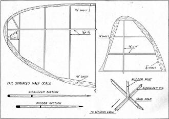
Tail surface parts are of simple design and construction. The
stabilizer is made in one unit, rounded in front and tapered at
the rear. The rudder is put together in the same manner as the stabilizer,
using the materials specified. Both units are covered with bamboo
paper, water sprayed, and doped three times. The perspective sketch
shows the manner in which the rudder post is notched to fit the
middle rib of the stabilizer. Cement this section securely.
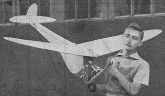
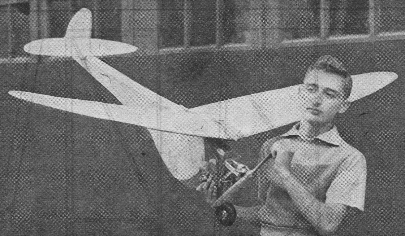
Here's Marty Powell with his Brown-powered, single
wheel "Guppie." The ship, which may be flown with any 1/5 or 1/6
h.p. engine, is covered entirely with bamboo paper. Construction
is rugged, yet light.
Assembly and Flying
Before covering the body, attach the 1/8" dia. dowel in the position
shown. The fuselage is covered, one side at a time, with plain bamboo
paper and is then water sprayed and doped.
Attach your air wheel and solder tin washers in place to prevent
the wheels from having too much side play. A wire hook cemented
at the extreme end of the fuselage assists in holding the tail surfaces
down by means of rubber strands extending between the dowel and
the hook. The wing is placed on the metal plate. Rubber strands
extending from the front hook, across the top of the wing, and to
the rear hook holds the wing in position.
Make it a point to always keep fresh rubber bands handy for use
on the wing and tail surfaces. Don't try stretching the bands too
tight when fastening the surfaces. Under such stress the bands may
give way in mid-air.
Painting your model is, of course, optional. Inasmuch as the
"Guppie" is by no great shakes a show-off model, the matter of doping
it up like a Technicolor production is unadvisable. As mentioned
before, weight is the biggest factor in gas job construction. So
wherever fractions of an ounce can be eliminated, the better the
endurance possibilities.
Because of the simplicity of the construction of the "Guppie,"
many modelers will probably attempt to build this ship as their
initial effort. The writer in that case, with your kind indulgence,
is offering some good advice as to the proper method of handling
gas jobs.
Use ordinary precautions before test hopping and endeavor to
obtain the longest glide possible. The most important phase is in
getting the proper adjustment of the surfaces.
Under no circumstances attempt to fly the ship when the wind
is blowing up hard. Simply because you've seen a model climb rapidly
in the face of a stiff wind is no reason to assume that a craft
with more power than an ordinary rubber job will do twice as good.
Choose a calm day for the first test flights. Pour just enough
fuel in the tank for a few seconds flying. If your ship is equipped
with a timer the fuel allotment may be greater, so it won't be necessary
to refill too many times.
Spin the prop, and when the motor starts revving adjust the needle
valve for smooth running.
Face the ship into the wind, open the throttle wide out, and
with a slight shove send the ship on its way.
Bill of Materials
Six strips 1/8" by 1/4" by 36" for lower longerons and cross
braces
Five sheets 1/16" by 2" by 36" for wing ribs
Four strips 1/8" by 1/4" by 36" for ribs in tail surfaces
Two strips 1/4" by 1/4" by 36" for the leading edges
Two strips 1/8" by 1/4" by 60" for fuselage longerons
Two strips 1/4" by 3/4" by 36" for wing spars
Two strips 18" by 1/4" by 36" for rear spars
Two strips 5/16" by 1 1/2" by 36" for trailing edges
One strip 1/8" by 1/4" by 36" for spars in elevator and rudder
One strip of sheet 1/8" by 2" by 36" for wing tips
One strip 1/4" by 5/8" by 36" for motor mount; hard pine
One sheet 1/4" by 2" by 36" for leading edges
One sheet 1/8" by 2" by 36" for trailing edges
One length of 1/16" dia. wire for hooks, length of 1/8" dia.
wire for landing gear, one 4 1/2" dia. air wheel, five sheets of
bamboo paper, tin for wing mount, one length 1/8" dia. dowel, dope,
cement, pins and complete soldering equipment.

Guppie Free Flight Gas Plans
(plate 1)
Guppie Free Flight Gas Plans
(plate 2)
Guppie Free Flight Gas Plans
(plate 3)

Guppie Free Flight Gas Plans
(plate 4)
Notice:
The AMA Plans Service offers a
full-size version of many of the plans show here at a very reasonable cost. They
will scale the plans any size for you. It is always best to buy printed plans because
my scanner versions often have distortions that can cause parts to fit poorly. Purchasing
plans also help to support the operation of the
Academy of Model Aeronautics - the #1
advocate for model aviation throughout the world. If the AMA no longer has this
plan on file, I will be glad to send you my higher resolution version.
Try my Scale Calculator for
Model Airplane Plans.
Posted August 1, 2015
|