|
Many thanks to website visitor Bob Balsie, who graciously offered
to scan this article (with many more to come)
from his collection of Young Men magazine. The front page
tag line above the title proclaims:
 "Now!
'Air Trails Hobbies for Young Men' Expands into Young Men • Hobbies • Aviation • Careers"
The final issue of Air Trails - Hobbies for Young Men
was October 1955, so this November 1955 edition of Young Men
- Hobbies, Aviation, Careers was the first in a series that
ran for 13 months. "Now!
'Air Trails Hobbies for Young Men' Expands into Young Men • Hobbies • Aviation • Careers"
The final issue of Air Trails - Hobbies for Young Men
was October 1955, so this November 1955 edition of Young Men
- Hobbies, Aviation, Careers was the first in a series that
ran for 13 months.
Two things caught my attention here. First it that the article
is Part VIII, which means the previous seven were printed in
Air Trails. Second is the photo of Claude McCullough of Ottumwa,
Iowa. Ottumwa is the town from which M.A.S.H.'s
Radar O'Reilly hearkened.
How Construction Affects the Finish
Correct building techniques for any model project can mean an
easier, better finishing job; Paul tells how.
By Paul E. Del Gatto

San Francisco's John Talon turned out this magnificent
Meyers 145; took 2nd in 1955 Nationals' control line flying scale.
So far in this series on how to finish models you've heard from
some very well informed and experienced model builders. But little
emphasis has been placed on some of the general construction techniques
which directly or indirectly influence the finish of a model.
Some facts about the materials used come in handy for anyone
interested in building better looking models.
Balsa wood, our main construction material, is one of the most
difficult of wood surfaces when it comes to applying a good finish.
Couple this fact with the knowledge that balsa wood is cut several
ways for varying degrees of strength, flexibility and weight, and
the need for knowing how to select balsa becomes very apparent.
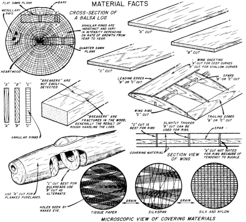
Look at the cross-section sketch of a balsa log. Note how it
is cut. To begin with any log that is sawed from the center outward
is known as a "quarter sawn" plank. Taking this plank and cutting
it into sheets will yield balsa which in model lingo is referred
to as an "A" cut. This type of sheet is most easily identified by
its flexibility and velvety feeling, and it is best used for planking
large areas such as the wing and stab leading edge surfaces or for
fuselages.
Logs that are sawn approximately tangent to the annular rings
are often referred to as a "tangent slash" or more commonly as a
"flat sawn" plank. Cutting sheets from this plank will yield "C"
cut balsa wood and an intermediary cut referred to as a "B" cut.
"C" cut sheets are instantly recognized by their speckled appearance
and exceptional stiffness, a quality which makes a "C" cut sheet
very valuable to a model builder. This stiffness is the result of
the laminated quality of the sheet due to the perpendicularity of
the annular rings.
Your "B" cut sheet is an intermediary cut between the "A" and
the "C" cuts which has its annular rings running diagonally, rather
than perpendicularly or tangent to the sheet. The "C" cut is best
for most model use where strength and rigidity are required. However,
"C" cut represents the smallest percentage yield of all the cuts
which can be obtained from a log. When "C" cut balsa is not available,
then use a "B" cut of slightly greater thickness to compensate for
the relatively lower stiffness.
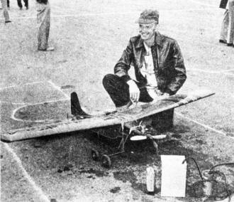
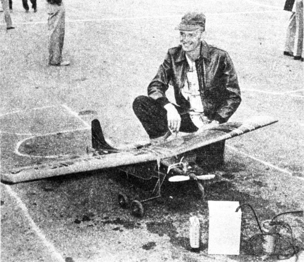
Claude McCullough of Ottumwa, Iowa, and new R/C,
4-wheeled Nats entry. A-1 finish.
Because of the spongy cellular structure of balsa it is subject
to "breakers." "Breakers" are cracks or fractures at right angles
to the grain which weaken the wood to a great extent. The bad part
about them is that they are not easily detected until the wood actually
breaks. Manhandling of the rough logs at the mill is the chief cause
of breakers.
Another interesting quality of balsa is its great strength under
direct compression. Rubber-powered model builders are perhaps more
keenly aware of this because of the extensive use of 1/8" sq. longerons
to produce a light structure, yet one strong enough to house a motor
of up to perhaps twenty strands of 1/4" flat rubber. (Cross bracing
balsa, diagonals and paper covering all serve to keep the longerons
in direct compression, to absorb the load of the very powerful rubber
motor.)
Thus the strength of balsa wood is determined to a large extent
by the method of cutting used. Also a determinant of strength is
the weight of balsa for each cubic foot. The average weight of balsa
logs is 12 to 15 pounds per cubic foot; for identical cuts, wood
that is lighter would be less strong and wood that is heavier would
be stronger. Indoor model builders use balsa wood that may weigh
as little as 4 lbs/cubic foot.
It is best to buy balsa wood when the most select cuts and light
weight grades are available to you at the hobby shops you deal with
and then store it at home for future use. This way, when you require
something special you do not have to settle for something which
isn't ideally suited to your needs.
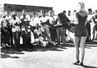
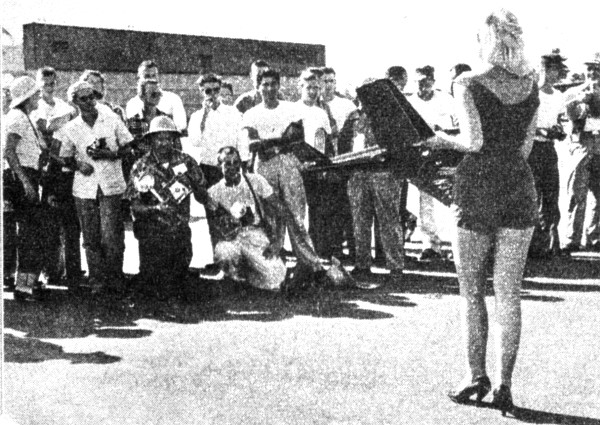
Note all the attention Tatone's Meyers model
receives from photogs at '55 Nats!
Besides balsa wood, the various covering materials used on all
types of models are well worth your attention. Covering represents
the final stage in the model's construction and knowing how to cover
and what material to use under varying circumstances is a "must."
Materials generally employed are tissue paper, light weight and
heavy weight Silkspan, silk and nylon. All these materials are porous
to varying degrees and this is one of the main reasons why doping
is required after the covering has been applied to a model frame.
If we were to examine a piece of each material under a microscope
we would notice that all the materials have a "grain" direction.
This grain direction is important for it serves as a guide to the
correct application of a covering material to either a frame or
solid wood surface.
Of the covering materials generally used tissue paper is the
most difficult to apply for several reasons. To begin with it can
only be applied dry because it lacks the "body" of the other materials
and when moistened tends to fall apart. Then too, its shrinking
qualities do not lend themselves very well in areas where uneven
shrinking is required. Round fuselages, curved wing planforms, wing-tips
and fillets are generally covered with one of the other materials
unless lightness is a serious determining factor in the model's
construction.
This particular advantage of light weight and the fact that an
airtight smooth dope finish can be achieved with fewer coats than
with the other materials makes tissue paper popular with rubber-powered
and small free-flight gas model plane builders. The disadvantages
possessed by tissue paper can be offset a great deal by exercising
particular care on sharply curved areas.
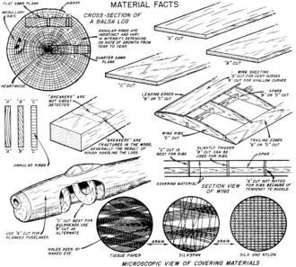
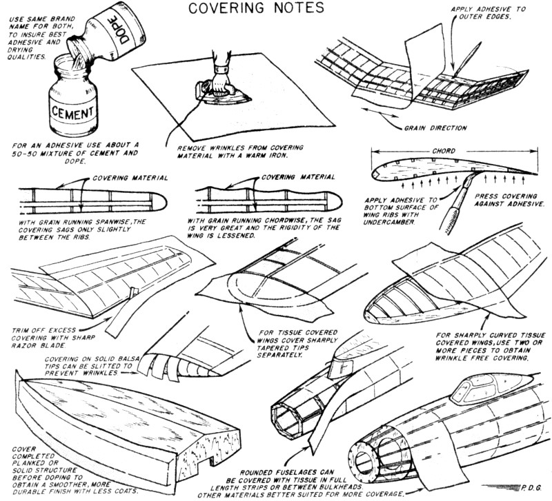
Material Facts
When applying covering to a wing we generally have two surface
areas to cover: an upper and lower wing curvature. Prior to covering
prepare an adhesive of approximately a 50-50 mixture of cement and
dope. With a warm iron (not too hot) press out any wrinkles that
may have been put in the covering material through folding or mishandling.
Whether you cover the top of the wing or the bottom of the wing
first or one panel at a time makes little difference.
Beginning at the wing center joint and covering just one wing panel
at a time, apply the adhesive only to the outer edges of the wing
panel and wing joint for several rib stations and lay the covering
on with the grain running in the same direction (parallel) as the
leading and trailing edges of the wing. Pull the covering taut in
all directions until all the wrinkles have been removed. Then follow
the same procedure until the entire wing panel has been completed.
Remove the excess covering material with a sharp razor blade.
When covering flat surfaces such as fuselage sides, the entire
side can be covered with one whole sheet providing the covering
material is sufficiently long. However, curved fuselage sides must
be covered in smaller sections to minimize wrinkles. If tissue paper
is the covering material use only one full-length strip or do one
bulkhead section width at a time; for Silkspan, silk or nylon the
area covered can be doubled and sometimes tripled.
Silkspan differs in that the main fibers intersect each other
in clusters running diagonally with the grain, but they are more
widely dispersed and held together by a loosely woven arrangement
of fibers running against the grain. These differences explain its
better shrinking qualities; the stronger fibers enable Silkspan
to be applied wet to a model.
Silk and nylon are entirely different in structure from either
tissue paper or Silkspan and are the most desirable of all the finishing
materials to use from the viewpoint of strength and covering qualities.
The fibers of silk and nylon are uniformly arranged and perpendicular
to each other; the grain is determined solely by the closer spacing
of the fibers in one direction than the other. Another interesting
feature is that the fibers go over and under one another. On curved
fuselages or pylons it is almost always possible to cover a whole
side at once with silk or nylon, and it can be applied wet for maximum
flexibility of use.
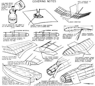
Covering Notes
Posted October 10, 2015
|