|
 1954 was just a decade after
World War II, during which time the Army Signal Corps introduced a method of
printing - or etching - metallic circuit conductors on an insulator substrate, and
thus was born the printed circuit board (PCB). The first boards used a phenolic-paper
laminate, which is the shiny brown substrate material that is still found in some
industrial applications like motors and control panels. Ferric chloride was used
to etch away the copper foil not masked off with photoresist chemicals. I made many
crude PCBs using a resist ink pen to draw circuit traces and component mounting
pads, then etched away the exposed copper with ferric chloride purchased
at Radio Shack. This line from the article is reminiscent of people who remarked
similarly about the first televisions and computers: "One of the first questions
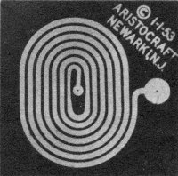
that arises is: 'What good is it and what do I gain by using it?'" Printed inductors
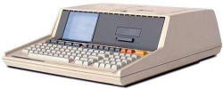
were already being used, as the photo shows. Back in the mid 1980s, I programmed
an HP 85 computer, using
HP BASIC
(aka Rocky Mountain BASIC), to draw printed inductor patters in the engineering
development lab where I worked for Westinghouse. A built-in thermal printer spit
out the image on paper, and then the image was transferred onto clear acetate in
a copying machine for use in the photoresist exposure process. Anyone else remember
using one? 1954 was just a decade after
World War II, during which time the Army Signal Corps introduced a method of
printing - or etching - metallic circuit conductors on an insulator substrate, and
thus was born the printed circuit board (PCB). The first boards used a phenolic-paper
laminate, which is the shiny brown substrate material that is still found in some
industrial applications like motors and control panels. Ferric chloride was used
to etch away the copper foil not masked off with photoresist chemicals. I made many
crude PCBs using a resist ink pen to draw circuit traces and component mounting
pads, then etched away the exposed copper with ferric chloride purchased
at Radio Shack. This line from the article is reminiscent of people who remarked
similarly about the first televisions and computers: "One of the first questions
that arises is: 'What good is it and what do I gain by using it?'" Printed inductors
were already being used, as the photo shows. Back in the mid 1980s, I programmed
an HP 85 computer, using
HP BASIC
(aka Rocky Mountain BASIC), to draw printed inductor patters in the engineering
development lab where I worked for Westinghouse. A built-in thermal printer spit
out the image on paper, and then the image was transferred onto clear acetate in
a copying machine for use in the photoresist exposure process. Anyone else remember
using one?
Radio Control News
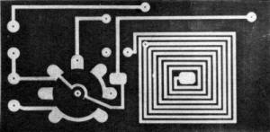
Examples of etched printed circuits. Although only 0.0014 often
in. thick, 1/64 in. wide copper strip will carry 3 amps, 1/8 in. up to 15 amps.
Printed circuits and etched wiring, new items, subminiature capacitors, club
news, and late trends.
By E. J. Lorenz
This is the first - and the first in print in our field, we believe - of a series
of discussions and how-to-do-it chats on printed circuits, or etched wiring, as
applied to model work. Just after World War II, the U.S. Signal Corp announced a
new method of "printing," or, to be more exact, etching conductor lines on an insulated
base material. In the past three or four years this method of making electrical
and electronic assemblies has found its way into government and commercial fields,
and recently into our own field of RC work.
Basically, this is what we have: an insulated base of phenolic-paper laminate,
upon which is a conductive layer of copper foil. This copper, which measures .0014
in. thick, is bonded to the base material under heat and pressure. The base may
be had in thicknesses from .005 in. to 1 in. thick, although the most common sizes
are 1/32, 1/16, 3/32 and 1/8 in.
Commercially, a conductor pattern is imposed upon the copper by silk screening,
stenciling or by means of what is known as photo resist. This pattern then forms
a barrier, or resist, to the etching solution, which is ferric chloride. The ferric
chloride solution eats away the balance of the exposed copper. The resist pattern
is then removed by solvents or scrubbed off with steel wool and we have left the
copper pattern such as seen in the accompanying photograph.
To one who has first seen such a circuit, the thought might occur that such thin
copper would not be able to carry much current. However, the following figures will
give you an idea of what can be expected:
The current given, based on .0014 in. thick copper, is that amount needed to
cause failure of the copper by excessive heating. However, one half of that amount
for a given size line is perfectly safe and is many times more than is needed for
RC work.
One of the first questions that arises is: "What good is it and what do I gain
by using it?" The final product is the ultimate in neatness. Done commercially,
each and every finished card is precisely the same, thus achieving a uniformity
heretofore almost impossible. Coils can be made in this way and positioned in the
circuit so that the inductances and capacitances involved are the same on each card,
thus reducing testing time and de-bugging. Also, there are no loose wires to break
or become entangled. We have in effect a "two dimensional" wiring layout. Components
such as resistors, capacitors, etc., are then placed in position in holes which
have been drilled in the small "lands" where connections are made to the conductor.
Some manufacturers place eyelets at each point of soldering.
Here we have a word of caution: do not use a heavy hot iron when making the solder
connection. We've found the popular Ungar pencil iron with a 1/8 in. diameter tip
in the 37-1/2 watt heating element to be an ideal iron. For solder we recommend
No. 18 gauge Ersin 60/40 solder. This low melting point solder can be obtained from
most radio supply houses or from Control Research.
Begin soldering by first heating the component lead slightly and then touching
the iron to the copper pattern at the time the solder is applied. Too much heat
will cause the bond between the copper and base to break loose, or even blister
the base material. When soldering a component into an eyeleted hole, such as is
used on the North American receiver, it is important to make sure the solder flows
not only from the eyelet to the component lead but also from the eyelet to the conductor
pattern.
Besides the conventional conductor patterns for receivers or transmitters, we
also have, in this new medium, excellent means of making limit switches or rotary
commutators or sequencing switches. In the past, segments were made by cementing
thin pieces of brass, copper or tin to a base material. This method, while workable,
is crude at best. Our new method is more precise. The bond strength between copper
and the base is better and the copper segments are thin enough vastly to improve
brush operation.
We hope this gives you a little idea of the possibilities of this method of construction.
Tune in next month for more design and some construction information.
New Items
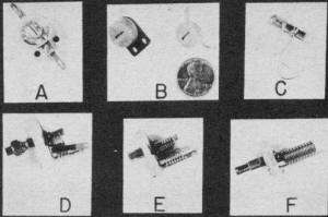
Variable lightweight capacitors, described in the copy. The size
of these ultra-small units may be compared with the Lincoln penny, in center.
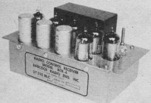
Six-tube receiver, three sealed relays. All controls, via compound,
elevator trimmer.
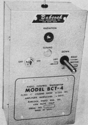
Much awaited multi-channel Babcock X-mitter. Note control stick,
the right side of the case.
This month we continue our presentation of the various components used in RC
work, with a review of miniature and subminiature variable capacitors for both receiver
and transmitter work. Strictly speaking, not all of these are "new items," but are
best grouped for the sake of clarity and cohesiveness.
Capacitor A is the familiar ceramic variable as made by Erie or Centralab. Adaptable
for either receiver or transmitter tuning, they come in ranges from 1.5 to 7 mmf
and up to 7 to 45 mmf. The Centralab unit is type 822 and the Erie unit is type
TS-2A. B shows the Erie type 557 which is a very small and lightweight trimmer.
This type may be had on a plastic base as shown on the left, or minus the base as
shown on the right. Good for receivers or low powered transmitters. In sizes from
8 to 50 mmf. Item C is a Centralab type 829 tubular trimmer, available in ranges
from .5-3 mmf to 1.5-10 mmf. Excellent for trimmer use, it is compact, lightweight
and may be mounted in a single round hole. D is the standard APC air trimmer made
by Hammarlund in a wide variety of values. E. F. Johnson also make a similar type.
Air trimmers of this type are recommended for transmitters, frequency meters and
wavemeters. Also okay for receivers if the size and weight can be tolerated. Type
E is a Hammarlund MAPC model. This is a miniature version of the previously mentioned
APC air trimmer. Available in a wide range of values. For the ultimate in subminiature
transmitter design we have the E. F. Johnson model M, as shown at F. This ultra
compact and lightweight air trimmer comes in four sizes in the conventional single
type, ranging from a maximum of 5 to 20 mmf. Also made in a differential and butterfly
model for builders having special applications for these types.
All of the above mentioned variable capacitors may be obtained from your local
radio supply shop, although some may have to be specially ordered. Control Research,
Berkeley Models, Ace Radio Control, Essco and other RC suppliers can also serve
you with some of these items.
The latest news in batteries is the new Burgess 1-1/2 volt Heavy Duty Industrial
cell. Available at present in the D size, this cell is made of a completely new,
artificial mix. This revolutionary mix increases shelf life, life under service
and the recuperative powers of the cell. This new cell should be a "must" for Large
B and Class "C" RC models. Available through your local Burgess dealer or distributor.
Electronic Specialty Supply Company of 58 Walker St., New York City, now has
a new relay tube for our two-tuber set. Known as the MPC-1, this tube has a 40 mil
filament and will pass over 3 mils through a 5,000 ohm relay. Similar in size to
the familiar XFG-1, this $1.95 hard tube should increase the relay tube life to
near infinity, barring breakage, and also give increased efficiency.
As this goes to press we learn of a new producer of tuned reed relays. Radio
Control Specialties of 377 W. Eighth Street, Eugene, Ore., should now have these
ready for the market.
Babcock Radio Engineering Co., Van Nuys, Calif., does it again. A newcomer to
the model radio control field, this firm has long been a supplier of target drone
equipment to the government and builders of commercial and industrial receivers
and transmitters. Their latest addition to the success of RC work is a three-channel
unit giving rudder, elevator and engine control. The 2-7/8 x 3 x 5 in., 16 oz. receiver
has a range of two miles, is virtually crash-proof and features all the same type
tubes for ease of replacement, and its "one adjustment" tuning feature makes it
the acme of simplicity to operate. The hand-held transmitter features a four-position
control stick, to give realistic "feel" to the operator. The transmitter also features
one tuning adjustment and a radiation indicator. The 300, 720 and 1,620 cps tones
are amplitude modulated up to 85 percent. For the rabid RC fan and builder this
looks like the ultimate in model radio control units. The pictures show the excellent
design and workmanship on the Babcock BCR-4 and BCT-4.
We've just received the latest catalogue sheets from Ace Radio Control of Higginsville,
Mo., and find they are ideal advertisements for the novice in the field. Photographs
of all kits offered give the buyer a first hand picture of what he is getting. Not
a bad idea.
Club News
William Rassbach of 624 Clyde St., Pittsburgh, Pa., dropped us a short line on
the doings of a few of the members of the DC/RC club. Leo Miller controls his 5-ft.
Arden .199 powered job on 220 mc. While on the subject, Carl Hermes of Arlington,
Tex., wants some information on 220 mc RC equipment. This might be a chance for
the DC/RC boys to do a little education work on a frequency other than 27 or 52
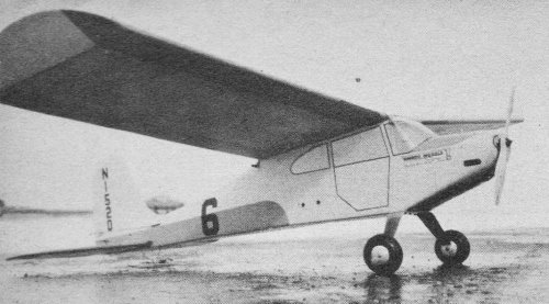
mc. Jim Reed, of the same club, has K & B .15 powered semi-scale Cessna L-19
with a three-tube receiver; operates proportional control on the rudder and elevator.
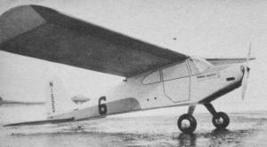
Aeronca-type Live Wire Champion, 56 in. span, 600 sq. in, area,
for engines of .15 to .19 displacement. Has both elevator and rudder controls.
While not exactly concerning club news, we did talk to Art Lagrange of Wappingers
Falls, N. Y., recently regarding the use of a gas tube as the first stage of a reed
receiver. Seems as though Art has a very nice receiver using this arrangement which
also operates a Sigma relay on the RF carrier. This is in the plate circuit of the
RK-61 in the first stage. To go one farther, we note in the British publication
Aero Modeller that one of their chaps has operated an ED reed bank from
a single XFG-1 and has obtained about 1,000 ft. range.
From Albuquerque, N. M., we are reminded of a very important safety item. This
concerns the sharp end of the vertical wire antennas emanating, unsuspected, from
the camouflaged confines of your model. Personally, we bend a 1/4 in. diameter loop
on top of the antenna, but it just never occurred to us to mention it before. A
small balsa sphere, painted yellow, red or orange and attached to the tip end also
should be satisfactory. Let's keep looking into the safety angles; they're important!
It seems that we're missing out on some top notch information when we fail to
hear from RC clubs within large engineering organizations. We know they exist but
for some odd reason they keep to themselves. How about hearing from some of these
groups? One thing we've found out recently is that too many individuals or groups
are hesitant about divulging their "secrets." During our many years of modeling
and manufacturing, we've found this to be one of the quickest ways to have a good
thing die a natural death. Get your idea into print and it will help both you and
the reader.
The Radio Control Club of Detroit is out to make the Detroit area the RC spot
of the East. They have a fine perpetual trophy. All persons interested, no matter
where they live, are urged to write to E. S. Kratzer, 1112 Book Bldg., Detroit,
Mich., for information about this year's meet. The novice flier is urged to attend,
along with the expert, since there will be separate groupings for each class. In
this way the beginner has a real chance. An excellent idea to get RC contests rolling,
and not have them just another addition to a larger contest.
Posted June 3, 2024
(updated from original post
on 3/9/2014)
|