|
Website visitor Jim P. wrote
to ask whether I would scan the Tenderfoot article in the March 1969 American
Aircraft Modeler for the Musketeer, a 1/2A profile control line model for beginners.
Mr. Jim Davis designed the model and drew the plans.
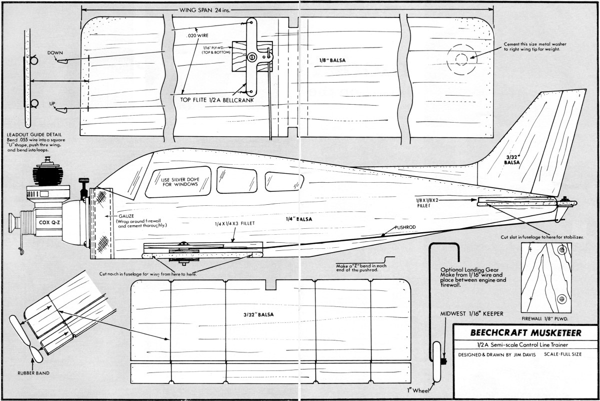
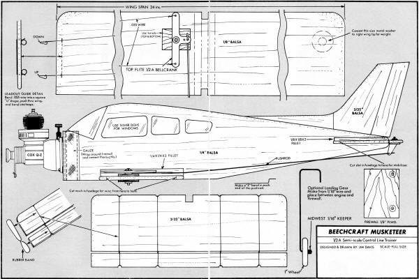
Musketeer
 by Jim Davis by Jim Davis
Beechcraft's biz-and-sport plane makes good controlliner trainer for 049 engine.
Plan is full size[originally].
THE Musketeer, a common sight at local airports, is a popular craft for business
or sport flying and flight training.
In a model, a good trainer usually must depart from scale because of the necessary
change in nose and tail lengths, and the proper location of the C.G. (center of
gravity). In this case, the Musketeer fuselage is a near-perfect scale profile.
Only the wing and stabilizer area had to be changed to obtain gentle flying characteristics.
The Musketeer model construction was made as simple as possible to keep beginners'
problems to a minimum. The secret of a good flying model is proper alignment; in
this case, most of the construction is done on a flat board.
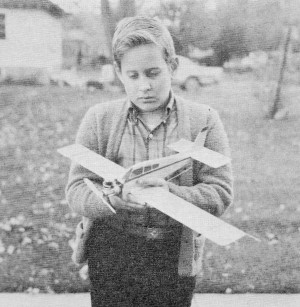
Do a neat job putting on trim and decorations and your ship will
gain respect at any flying site. Note muffler. Won't miss noise!
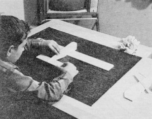
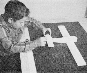
Proper alignment is important on any flying model. With wing
laid flat on the building board, the stabilizer is lined up.
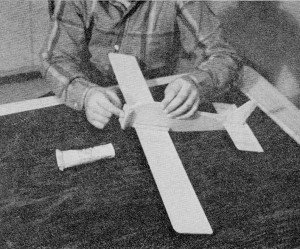
It is easy to glue fin on straight if you sight carefully along
fuselage after ship has been placed flat on your building board.
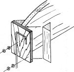
The plywood firewall (motor mount) is glued against front of
fuselage. Note the sturdy supports and the wing fillet pieces.
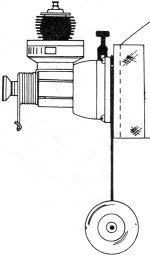
If landing gear is used, strut clamps in place between engine
tank and motor mount.
Detail of engine mount. Washers tilt engine thrust-line toward
the outside of circle.
Every beginner has trouble installing elevator hinges properly, yet this is one
of the most important phases of the construction. They must move freely in order
to have good control of the model. The elevator hinge problem was solved by installing
rubber bands in a figure-eight fashion. The method is simple and it is less likely
that
hinges will break in a crack-up than if cloth is used. This hinge method was
used for years by the author for emergency repairs when flying in combat competition.
CONSTRUCTION
The plans are full-size. Instead of cutting up your magazine, take a sheet of
tracing paper and tape it to the magazine page with masking tape, then carefully
trace the parts. The tracings can be cemented to the wood with rubber cement, then
cut out. If you have access to a jig saw or band saw, it will be easier to cut out
the 1/4" fuselage side. Make sure all the parts are cut accurately since they key
together and align themselves. The tracing paper can then be peeled off and the
remaining cement rubbed off with your finger.
The wing is made of 1/8 x 3 x 24 balsa.
Mark the center of the piece (12") and place the center portion of your tracing
there. The tracings for the wing tips are then placed at the ends of the balsa piece.
If you think the wing has an odd shape, take a look at a real Musketeer. It has
the same shape.
Pin the wing down to a flat board, then apply cement liberally to the center
of the wing and set the fuselage in place. Add the 1/4 x 1/4 x 3 fillets to each
side and hold in place with pins. Use a small triangle to be sure the fuselage is
exactly vertical. Apply cement to the center of the stabilizer and slide into position
in the fuselage slot. Use your triangle again to be sure the trailing edge of the
stabilizer is at right angle to the fuselage. Measure the distance of each tip down
to the board to be sure they are the same. This is to be sure the stabilizer is
parallel to the wing.
Add the two pieces of 1/8 x 1/8 x 2 fillets.
Cement the three vertical fin parts in place. If desired, the trailing edge of
the rear piece can be offset 1/8" to the right to give better flying-line tension.
Apply cement to the back of the plywood firewall and also to the two 1/2" triangles
and set them in place. Hold with pins. Be sure the firewall is up tight against
the front of the fuselage.
Cement one of the 1/16" plywood pieces to the top of the wing at the bellcrank
location. After you are sure all of the cement is dry, remove the model from the
board. Cement the second 1/16 plywood piece to the bottom of the wing.
Cut a 2 x 4 strip of ordinary gauze bandage and cement it to the front of the
firewall and around the sides. This reinforces the engine mount. Coat the top of
the gauze with cement. It would be best at this point to allow everything to dry
overnight. Then begin painting.
Since your Musketeer is being built for flying, not for appearance, keep the
painting to a minimum. The fillets on the wing and stabilizer can be carved to triangular
shape or left square. First, sand all surfaces and round all edges with fine sandpaper
or 6/0 garnet paper, then apply a coat of clear dope. After it dries, sand lightly
and apply two more coats of clear dope. When dry, apply the color dope. Since the
wing is a long, flat sheet, the shrinking qualities of the dope may warp the wood.
To prevent this, paint only half of one side then the entire other side; finally,
paint the remainder of the first side. If a warp should develop, hold the wing over
an open pan of boiling water and let the steam penetrate the wing. Do this to both
sides then pin the wing panel down to a fiat board.
After the final coat of dope has dried, the controls and engine can be installed.
Mount the horn in the elevator then bend the pushrod, using the fuselage side view
on the plan as a guide. Insert one end of the pushrod into the horn and the other
end in the outer hole of the bellcrank. Set the bellcrank on the platform 1/16 plywood)
and mark the location of the mounting screw with a pencil. Drill a 3/32 hole into
both plywood pieces and wing.
Bend loops in the leadout wires and attach to the bellcrank. Mount the bellcrank
in place. Bend the wire leadout guide as shown on the plans and insert the leadout
wires through it. Cement a metal washer to the bottom of the wing on the right side.
This counterbalances the weight of the flying lines. Instead of a metal washer for
weight, you can use 1/4 oz. of modeling clay.
Use #3 wood screws to mount the engine. Place a #3 fiat washer between the two
left engine mounting lugs and the firewall for engine offset. This points the engine
slightly to the right towards the out-side of the flying circle) for proper line
tension. If landing gear is used, two wash-ers may be necessary.
If you care to have a landing gear, one can be made from 1/16 music wire and
mounted between engine and firewall.
The landing gear is an optional feature mainly because it is difficult to take
off on grass with a small model, while concrete will allow a takeoff but can cause
severe damage in a crack-up. Therefore, grass is the preferred surface for a beginner.
If grass, the model would take off by hand launch. When ready for takeoff be sure
the elevator is neutral, then have your helper run with the model with the nose
pointed level and slightly to the right. He should also be keeping the lines tight.
Have him run until the model flies out of his hand and you be ready to step back
if the lines go slack.
Let the model fly by itself and you correct the level of flight only when necessary.
Most beginners will tend to over control. To prevent this, hold your arm straight
out and raise and lower your whole arm instead of using your wrist to control the
model. Above all, don't be afraid of a crack-up. If your model hits the ground,
pick it up, dust it off, and try again. Any damage can be easily repaired with a
little cement. Your model will last a long time because of its simple, wood construction.
MATERIAL LIST
1 pc. 1/8 x 3 x 24 balsa
1 pc. 1/4 x 3 x 12 balsa
1 pc. 3/32 x 3 x 12 balsa
2 pcs. 1/4 x 1/4 x 3 balsa
2 pcs. 1/8 x 1/8 x 2 balsa
2 pcs. 1/2 x 1-3/4 balsa triangle
2 pcs. 1/16 x 3/4 x 1 plywood (thicker wood may be used)
1 pc. 1/8 x 1-1/4 x 1-3/4 plywood
1 pc. 2" X 4" gauze
1 1/2A size bellcrank & horn
4 # 10 rubber bands
1 pc .055 x 12 music wire
2 pcs .020 x 14 music wire
4 #3 x 3/8 wood screws
2 # 3 flat washers
Clear dope
Color dope
1 .049 engine (see your engine instructions for prop size)
1 1/2A·size control handle and lines
1 can 1/2A fuel
1 fuel pump
1 1-1/2 volt starting battery
1 battery cord and clip.
<click image for larger version>
Notice:
The AMA Plans Service offers a
full-size version of many of the plans show here at a very reasonable cost. They
will scale the plans any size for you. It is always best to buy printed plans because
my scanner versions often have distortions that can cause parts to fit poorly. Purchasing
plans also help to support the operation of the
Academy of Model Aeronautics - the #1
advocate for model aviation throughout the world. If the AMA no longer has this
plan on file, I will be glad to send you my higher resolution version.
Try my Scale Calculator for
Model Airplane Plans.
Posted January 26, 2011
|