|
Canard airplanes - those with
the horizontal stabilizer forward of the wing - have been around for a long time.
In fact, the Wright Brothers' airplanes were canards. They tend to go in and out
of style. It seems all of a sudden articles will appear in all the model magazines
for a couple months, and then they disappear for a few years until something makes
them popular again. For full-size airplanes, it probably wasn't until
Burt Rutan came on the scene in the early 1970s with his Varieze (and later
the Long-EZ). That started
another wave of canard models. Than, as usual, they faded from view. A decade later,
the Beechcraft Starship
emerged as the first commercial jet canard. The
Eurofighter is now the most prominent
canard. For a particular configuration to really rule the model airplane scene,
it needs to win big at national and international contests. So far, that has not
happened. Maybe you are just the guy we have been waiting for to create that new
paradigm with canards. Here is some design information that might help you get there.
Ironically, there is an article on Dick Sarpolus' "big
c" canard in this month's Model Aviation (August 2014). You might also be interested
in the "Alain's Duck" plans.
Canard Design Pointers
Looking for something new and different in RC designs? Then add a canard to your
must list for '68!
Capt. Ronald VanPutte
|
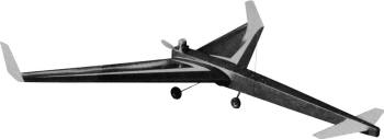
The extreme sweep and taper of the wing are evident in photo. Foam construction
makes it easy, reports the craft's designer.
|
If you ask yourself, "Why would anyone want to build something as unconventional
as a canard?" - then you are missing the point. The main reason for building a canard
should be that you want to get out of the rut and do something different.
My interest in canards began when I was looking for a problem to give students
in the stability and control course at the Air Force Institute of Technology, Dayton,
Ohio. All Air Force officers, they were graduate students in a combined Aeronautical-Mechanical
Engineering program. I wanted a problem that was challenging and interesting. The
design of a canard airplane seemed ideal. I told my students that if the design
looked promising, I would build and fly an R/C model of it before they graduated
in mid-March, so they could see the result.
Construction began about a week before Christmas, and the plane was completed
in time to be displayed at the Toledo R/C Conference. The first day warm enough
for the plane to be flown was March 9. We gave it a try with Don Lowe at the controls.
Results were extremely gratifying. The plane had three flights and exhibited no
nasty tendencies in normal flight maneuvers. Normal stalls were very gentle. Only
bad tendency the airplane has is in a deep stall recovery. On the third flight Don
pulled the airplane up steeply, as though he was going to loop it, and suddenly
chopped power. It fell through to a near-horizontal attitude, going into a classic
falling leaf stall with the wings rocking ± 30 degrees. The airplane would not recover,
no matter what Don did. I suspect this condition was caused by an unfortunate combination
of planform areas that will not be repeated. To date my canard has successfully
flown many times; it is as easy to fly as my Senior Falcon.
|
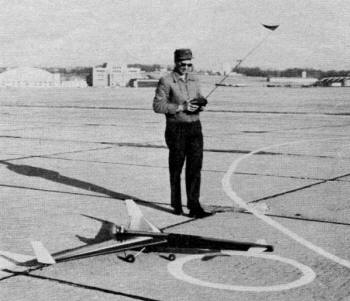
Don Lowe, acting as test pilot, prepares for takeoff on maiden flight. Among
interesting features is the short-coupled gear.
|
But, what about your canard? With the design points I am going to pass along,
every competent R/C builder-flyer should be able to design his own canard. Let's
talk briefly about separate parts of the airplane (wing, horizontal stabilizer,
vertical fin, fuselage and engine) and then discuss them as part of an integrated
design.
There is no reason why a canard's wing cannot be the same as the wing on a conventional
model. In fact, if you are crafty, the wing from your Taurus, Kwik-Fli, etc. can
be used. The horizontal stabilizer (including elevator) also can be conventional.
Or, you may wish to try something different and use an all-movable stabilizer as
on my canard. Remember, though, up elevator on a canard makes it pitch down!
The horizontal stabilizer should be about 20% of the area of the wing if it is
about the same distance from the wing as a conventional airplane. Make it slightly
smaller for longer tail moments and vice versa. Stabilizer should be a little smaller
than on a conventional airplane because it will be out of the wing wash and more
effective.
The vertical fin (including rudder) will, in general, have to be different. Do
not mount it on or near the horizontal stabilizer. A fin is used primarily to provide
directional stability to the airplane. It (or they) should be mounted as far behind
the center of gravity as possible to be effective. Since the horizontal stabilizer
and most of the fuselage are located ahead of the CG, they create a destabilizing
effect. Obtaining sufficient directional stability is one of the biggest problems
in canard design.
The fuselage will have to be somewhat different, more for esthetic reasons than
practical ones. You must admit a Sonic Cruiser fuselage would look pretty silly
going backwards. Seriously, the destabilizing effect of a forward fuselage can be
alleviated by making it a rather slender boom.
The engine should be operated as a pusher at the rear. If one mounted the engine
at the nose, a serious CG problem would result, requiring a large amount of ballast
at the rear of the plane. Attempting to operate the engine as a tractor, located
on a pylon near the CG, would cause trim changes from engine-on to engine-off. A
twin-engine canard with engines on the wing or on pylons to either side of the fuselage
and near the CG is certainly practical.
|
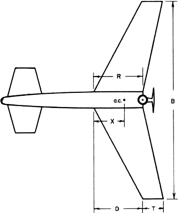
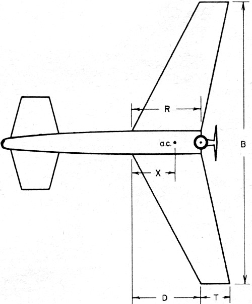
Figure 1.
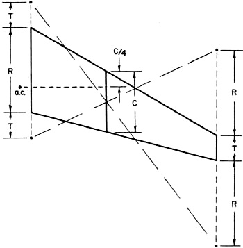
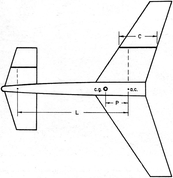
Figure 2.
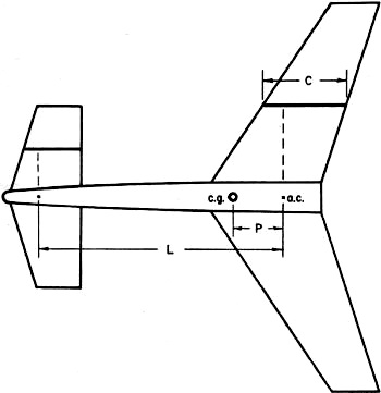
Figure 3.
|
This leaves one with a pusher being the most practical type of propulsion. The
problem in using a pusher layout is finding engines that will run backwards or in
finding sufficiently large pusher propellers. The largest commercially available
pusher prop is a 10-6 nylon (which is a bit small for engines of 51 cu. in. and
up). However, I used a 10-6 pusher on a Super Tigre 56 in a 7.5 lb. airplane with
reasonable success. The only time the plane lacked power was in the vertical maneuvers.
Now, what about the integrated design? You must put the pieces together so that
the airplane is stable and controllable. If you have doubts about how things should
be made, control deflection, etc., rely on experience and do what has worked before.
This may not sound technically exciting, but it works. General construction techniques
are the same in a canard, since all you do is rearrange basic aircraft components.
If you had success building and flying R/C airplanes, the canard design you have
in your mind will probably fly if the CG is properly located. The problem is to
find the proper location. Let's assume that you have your idea sketched on a piece
of paper, and it looks something like Fig. 1.
The first thing you must find is the location of the wing's aerodynamic center.
You may use equation 1 to determine X, the distance the wing aerodynamic center
is aft of the leading edge of the root chord (in inches). In the equation, R is
the root chord (in inches), B is the wing span (in inches), S is the wing area (in
square inches), D is the distance between the leading edge of the root chord and
the leading edge of the tip chord (in inches) and K is the ratio of tip chord to
root chord T/R.
Equation 1:
Equation 2:
Equation 3:
Equation 4:
Equation 5:

Equation 6:

You may easily determine the area of a trapezoidal wing by using equation 2.
The mean aerodynamic chord (C) of a trapezoidal wing is determined with equation
3. If your arithmetic is rusty, or you don't understand the equations, the wing
aerodynamic center may be determined graphically as follows: Draw an accurate picture
of one half of the wing as in Fig. 2. Extend the root chord in both directions an
amount equal to the tip chord. Extend the tip chord in both directions an amount
equal to the root chord. Draw two lines from the four points as indicated. The two
lines will intersect at the midpoint of one of the wing chords. This chord is the
mean aerodynamic chord C. Measure toward the leading edge an amount equal to one-quarter
of this chord. Project the point you've just located to the fuselage centerline.
This is the aerodynamic center of the wing. Both techniques for determining the
location of the aerodynamic center of the wing involve approximations but are accurate
enough for our purpose.
The author and his rare bird. The design resulted from a problem he gave students
at the Air Force Institute of Technology.
Locate the aerodynamic center of the horizontal stabilizer in the same way. Let
L, Fig. 3, be the distance between the aerodynamic centers of the wing and stabilizer.
Let S be the wing area and A be the area of the horizontal stabilizer. The CG should
be located, a distance P, ahead of the aerodynamic center of the wing as shown in
Fig. 3, where P is determined by equation 4.
Use of this equation actually places the CG ahead of where it should be for an
optimum balance of stability and controllability, but it does guarantee longitudinal
stability. After your canard has flown successfully, you may want to move the CG
slightly rearward. If it looks as though you can actually get the CG where you want
it, you are well on your way. However, if it seems like an impossible location,
without adding a lot of ballast, change your design until the CG is in a reasonable
spot.
It was mentioned earlier that obtaining directional stability was one of the
biggest problems in canard design. For this reason I recommend that the wings on
your canard should be either swept or a modified delta shape with vertical fins
on the wing tips. Either technique puts the vertical fins well rearward of the CG,
a condition mandatory for good directional stability. However, fins located on the
tips of even highly swept wings are still not as far back of the CG as vertical
fins on conventional craft. Therefore, each vertical fin should be about the size
of the vertical fin on a conventional airplane. A good rule of thumb, in deciding
how big to make the vertical fins, is equation 5. In the equation, V is the area
in sq. in. of each vertical fin, including rudder, and F is the distance from the
CG to the center of the vertical tail (in inches). The other terms (S, B) were defined
before.
The formula assumes you are using two fins; if you are using only one, multiply
the answer by two to get the required area of a single fin. If you insist on a straight
wing, make the horizontal stabilizer area about 40% of the wing area in order to
move the desired CG well forward, providing more distance between the CG and vertical
fins.
Another good rule of thumb in deciding how big to make the horizontal stabilizer,
or length of the fuselage, is to satisfy equation 6. All variables are as defined
earlier. For a conventional airplane, with a horizontal tail area to wing area ratio
of 1:5, this equation says the distance between the aerodynamic centers of the wing
and tail should be about 2.5 times the wing mean aerodynamic chord.
An additional reason for using swept or delta wings is that they exhibit a beneficial
dihedral effect. When an airplane is in a roll, it tends to side-slip to the inside.
Dihedral creates a rolling moment, tending to roll the airplane upright. Swept and
delta wings exhibit this characteristic. For example; the wing on my canard has
no dihedral, but the 35-degree sweepback provides dihedral effect. An advantage
in using a swept or delta wing and no dihedral is that the airplane will exhibit
the same dihedral effect when upright or inverted. Still another advantage is a
beneficial effect added to the airplane's directional stability.
Incidence angle of the horizontal stabilizer should be about 2-5 degrees greater
than that of the wing. The rule, used primarily so that the airplane tends to pitch
up when there is zero wing lift, has a good side effect. When approaching a stall,
the horizontal stabilizer stalls first and falls through before the wing stalls.
This is what makes a canard have gentle stalls.
Choice of landing gear type and location is almost arbitrary. It would probably
be a good idea to have the main gear well back to protect the prop. The nose gear
can be most anywhere on the fuselage. It could be considered as ballast and moved
about to get the CG in the right place.
That's it. I hope you are able to design your own canard after reading this.
Let me hear about your success or failure.
Posted January 31, 2022
(updated from original post on 7/26/2014)
|