|
In the late 1970s, I was working
on my private pilot license and dreamed of building a homebuilt airplane. The Bowers
Fly Baby biplane was the first choice based on my nearly non-existent budget since
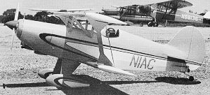
it was all-wood and used a 65 HP engine. What I really wanted was an EAA Acro-Sport
biplane. I was a member of the Experimental Aircraft Association (EAA) at the time
and first learned of it in their monthly magazine. This scale rendition appearing
in the November 1974 issue of American Aircraft Modeler magazine really
made me want to build one. Unlike the Pitts Special or the Christian Eagle, the
Acro-Sport can be tackled by most people of average building skills, and cost a
whole lot less for materials and powerplant.
An Airplanes and Rockets website visitor asked that I post this article for reference
while building the model from an old set of plans that he has. Hopefully, he will
send a photo of the completed craft once it's ready to fly.
EAA Acro-Sport
 The home-builders' aerobatic bipe that set the aviation world afire with
its good looks and superb flight performance is now a basement project for the modeler. The home-builders' aerobatic bipe that set the aviation world afire with
its good looks and superb flight performance is now a basement project for the modeler.
By Robert Schultheis
There's a little blue and white bipe sitting
over on the north end of the field that you are going to flip over. The EAA has
done it again." So spoke fellow flier Ken Hinkel at the Oshkosh 1972 EAA Fly-In.
With camera in hand I a\ran anxiously over to where it stood What a sleek little
bird, with one of the best looking paint jobs I'd ever seen. no checkerboards or
upside down names. Just long smooth black and yellow slashes for stripes over blue
and white. I stood there, flying a model of that biplane in my mind. One week later
the plans were drawn and I started building.
The EAA is the most cooperative on pictures and three-view drawings, right up
to the plans for the real thing, which are available from them.
 The plane has rather slim wings (narrow chord),
a fairly long nose moment and good tail areas. Try to keep the weight to six pounds,
although mine is seven pounds and flies fine. The plane has rather slim wings (narrow chord),
a fairly long nose moment and good tail areas. Try to keep the weight to six pounds,
although mine is seven pounds and flies fine.
The nose is built right into the fuselage and then cut away when fitted to the
engine elected. A little of the right front side of the cowl, back to F-3, is attached
to the front block F-1. This is doweled and screwed on, thus completely eliminating
a fiberglass cowl. The fuselage sides are 1/8" sheet balsa with 1/32" doublers contact
cemented to them. Former F-2 is really the front block, because the one-inch thick
noseblock is removable. F-2 gets cut out, as does the 1/8" sheet side in front,
to accommodate the engine use. This is done on the right front side, of course.
The sides are glued to formers F-3 and F-6B. This is done upside down, so that
the top of the sides provides a straight edge from which to work. Then add F-7B
and F-2. Draw center lines on all former pieces, as this facilitates their proper
location with relation to the sides. The top of the side is also the thrust line.
Now add F-2 and join the sides at the rear with the tailblock. Insert F-8, F-9,
F-10, F-11, and F-12. Top rear turtledeck can be made two ways: 3/32" sheet over
a 9 1/4" stringer or, as I did it (the lazy man's way), a 1/2" sheet from F-8 to
F-10 rounded off.
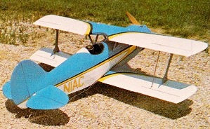 EAA Acro-Sport rear 3/4
view
EAA Acro-Sport Side View
The Acro-Sport's cowl is exceptionally clean, and is uninterrupted by the usual
vagaries of an exposed cylinder head, The Du-Bro Muff-l-aire keeps things quiet,
yet neat. The nose of a bipe gets lots of attention, so treat it with respect.
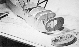
By superimposing partial formers on a box fuselage, the sweeping contours of
the cowl can be fabricated with less effort than with fiberglass.
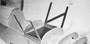
The bane of most bipes is the cabane "birdcage." The Acre-Sport simply employs
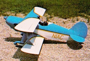
an aluminum blank to get the job done.
This view gives an excellent angle on those wings, which have a distinctively
short chord.
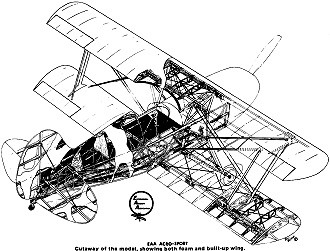
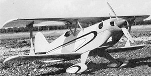
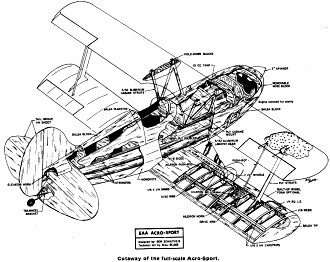
Cutaway of the Full-Scale Acro-Sport.
From F-10 to the rear of the fin is 1/16" sheet beveled on its edges to provide
a smooth fillet. The bottom is 3/32" sheet. I installed a Tatone mount on F-3 and
blocked off the left side of the cowl below the engine to get better circulation
around the head. This cooling of the engine is critical. Cut out enough cowl to
get air around the engine head. The opening on the front right hand side of the
cowl is cut out and lets air in. A rule of thumb is: Let at least twice as much
air out as goes in. I can't stress this enough.
The landing gear was made from one piece of 3/32" thick T-6 aluminum bent to
shape. The axle is of 5/32 wire which runs up to simulated shock absorbers. The
gear could be made entirely of wire and strapped to the hardwood blocks. This would
also be lighter. Wheel pants are Williams Bros. with a 1/4" balsa sheet around the
wheel (tapered to 1/16 at the front and back) epoxied between the two halves. It's
essentially a spacer to thicken the wheel pant, with a cutout for the wheel.
The cabane struts can be made two ways, either solid or as a strip. Bend up a
sheet of 3/32" T-6 aluminum after laying out and cutting "N" struts in their proper
location.
The second method is to use some 7/16 x 3/32" T-6 aluminum bent up to the sizes
shown on the plan. Then add cross struts with pop rivets, or epoxy to form an "N."
The cabanes are bolted with 4-40 screws and blind nuts onto the 3/32" ply plate
between F-5 and F-6. This ply plate is glued on top of the fuselage sides. Good
alignment of the cabanes is assured because they are made and checked on a flat
surface and then mounted on the fuselage. Shims may be added, if necessary, after
flying to get proper trim. The interplane struts are made from 1/16" plywood, then
sanded and sealed with Hobbypoxy. They are fastened to small brackets which are
epoxied in the foam or built-up wing.
Their placement fore and aft in the wing is not critical (± 1/4" is good enough)
but the spanwise location gives the proper slant to the strut between the wings.
These struts are placed outside (toward the top) of the brackets and have a 3-48
blind nut pressed in them. This blind nut is located and transferred through the
bracket. Use nylon screws, if available. They are strong enough for flying pressures
but will shear off, saving the wings, if ever necessary.
Now that the cabanes have been made and fitted, sheet and plank the fuselage.
I used 3/32" sheeting on gentle curves, (top and bottom of fuselage, rear sides,
etc.). Plank around the cheeks of the cowl with beveled 3/16" strips. The 3/16"
can easily be sanded to the correct thickness. This is only a small area on each
side of the nose. Blocks of balsa were used on the lower front nose. A sheet of
1/2" balsa on the lower center front blends in with the F-1 nose block.
Use your own judgment on where to fill, because it's easier to see than to draw
or explain. I still think this method of constructing the cowl is faster and cheaper
than a fiberglass one, which could crack or chip. There is a semi-circular shield
around the exhaust pipes on the real Acro-Sport. I simulated this with a piece of
3/8" balsa cut in a half-moon shape about 1/4" thick and glued on the bottom front.
The fin, rudder, stab, and elevator are of soft 1 /4" sheet. Hinges are Robart
hinge points which give a scale-like appearance.
The windshield was cut from a 13" Sig canopy. It blends perfectly with the fuselage.
The cockpit is edged with black 1/4" neoprene fuel line. This is slit and glued
on. A 2" diameter spinner finishes off the nose.
The wings can be of conventional built-up ribs and spars or of the foam type.
I chose foam, which is slightly heavier, but stronger for banging around. Foam wings
are old hat anymore, so I won't spend much time discussing their construction, other
than to say: Be sure to fiberglass at least a 6" wide band at the center section.
Both wings are straight with no taper. The top one is flat, the bottom has 3/4"
under each tip. Four 8-32 nylon screws hold the top wing to the cabanes. Two 10-32
nylon screws and a LE dowel hold on the lower wing.
Cutaway of the model, showing both foam and built-up wing.
By now you have spent some time constructing and you're ready to try all the
parts for fit. I put the whole plane together, uncovered. Fit the interplane struts.
Then, when satisfied, cover everything with light blue and white MonoKote. The aileron
drive rods connect the lower and upper wing ailerons. Use a Du-Bro Kwik-Link for
adjustment on one end and a solder link on the other. I slipped this rod into a
chrome-plated K&S 1/8" diameter tube, after applying some Silastic to the rod.
Push rods are your own option. Install the radio where you want it and you're set
to fly.
Balance at or ahead of the CG shown and give the little bird a try. Add power
slowly till the plane is moving, then get off the elevators and steer gently with
rudder. She'll fly off nicely at half throttle. Once airborne and heading out, pour
the coals to her. This little bipe is truly something to flip over.
Note: The Acro-Sport placed a respectable fourth at Jerry Nelson's Bipe Contest
this season, which speaks well of its potential in the new N.S.P.A. event.
EAA ACRO·SPORT
Designed by Bob Schultheis Technical Art by Bill Blake
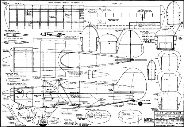
EAA Acro-Sport Plans
<click
for larger version>
Notice:
The AMA Plans Service offers a
full-size version of many of the plans show here at a very reasonable cost. They
will scale the plans any size for you. It is always best to buy printed plans because
my scanner versions often have distortions that can cause parts to fit poorly. Purchasing
plans also help to support the operation of the
Academy of Model Aeronautics - the #1
advocate for model aviation throughout the world. If the AMA no longer has this
plan on file, I will be glad to send you my higher resolution version.
Try my Scale Calculator for
Model Airplane Plans.
Posted July 15, 2024
(updated from original post
on 3/22/2012)
|