|
CO2
power for model airplanes gained a lot of popularity in the 1950s and throughout
the 1960s and then waned for some reason in the 1970s. The same trend was exhibited
in Jetex type engines. CO2 engines run off a cylinder of compressed carbon
dioxide gas, which were and still are readily available due to their use in air
rifles and pistols. A metal tube feeds the top of the engine cylinder where a metal
ball under pressure from the gas seals off the cylinder until the piston pushes
up on it. When the port opens, gas pressure forces the piston down to the point
where the gas is ejected at the exhaust port. Momentum from the propeller mass swings
the piston back to the top of the cylinder where it once again opens the ball valve
to start the cycle all over again. CO2 engines are very reliable and
easy to start since no ignition is required; however, the power-to-weight ratio
is fairly low. This 1962 American modeler magazine article presents plans, and
building and flying instructions for the "Fizz-Wizz."
See the "Push-Air
CO2-Powered Free-Flight" article from the February 1970 American
Aircraft Modeler and "CO2 Power
Is Coming Back" in the April 1969 American Aircraft Modeler. Here is a link
to my DP-03 CO2 motor.
Fizz-Wizz CO2-Powered model Airplane
 Clever approach to real ''gas'' flight designing
utilizes Herkimer's CO-2 motor
By Aubrey Kochman
With Herkimer Tool & Model Works' CO2
engine again in production here's a plane designed expressly for this novel powerplant.
The challenge of CO2 designing is
as rewarding as the flights attainable with this engine. Shallow climbing turns
and graceful glides to perfect three-point landings bring back the realism so long
missing from free flight. And no noise to bother your neighbors!
The engine maker offers rough limits for a suitable model suggesting wing area
be between 115 and 165 square inches - our Fizz-Wizz has 135. Allowable "bare" model
weight of up to 5 ounces (less engine, metal fuel cartridge, cartridge holder, fuel
line tubing and propeller) in our opinion is too high. Structurally Fizz-Wizz has
more than adequate strength yet weighs in at a low 2 1/2 ounces (5 with engine and
accessories ready to fly).
Since air temperature plays a part in the power output of this engine hot performance
in cold weather is not to be expected. Fizz-Wizz is meant to be a realistic sport
model rather than a high performance contest flyer. Test flights indicated, however,
that under ideal conditions (3 to 5-mph winds, temperature above 80 degrees) Fizz-Wizz
with a little additional trimming should turn in some really respectable durations.
Before starting construction bear in mind the weight and temperature factors.
Cold weather operations call for the use of the lightest possible balsa. For those
who year-around enjoy warm temperatures some additional weight can be tolerated
... although it is not recommended.
If you use light balsa your model should balance as indicated. The cartridge
holder location and its angle keep the plane's C.G. from shifting as the cartridge
empties. There is slightly over an ounce difference between a full and an empty
cylinder.
Build the tail surfaces last as a means of balancing the model. Should the model
turn out nose heavy, use a heavier grade of balsa for the rudder or stabilizer or
eliminate the cutouts in either or both surfaces. For tail heaviness reverse the
procedure ... use very light balsa, make the cutouts larger and apply a minimum
amount of dope.
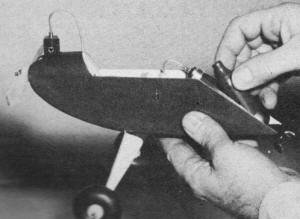
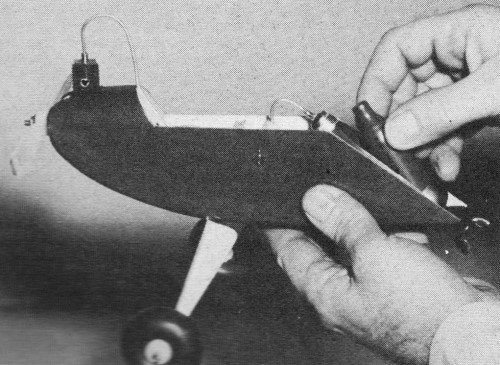
Loading a carbon dioxide fuel cartridge into Fizz-Wizz "power-pod"
is easy. Little chance of kinking or fracturing brass tube which carries gas to
C0-2 engine.

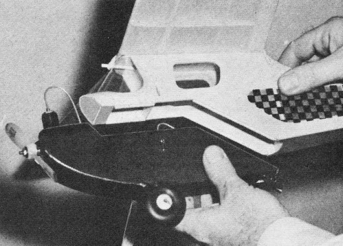
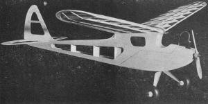
Attaching "power-pod" to fuselage. Full size working drawings
for Fizz-Wizz and Wizzo-Won are on Hobby Helpers' Group Plan # 362.
Fizz-Wizz frameworks.
Begin fuselage construction by cutting the two side pieces to shape; 4" wide
sheet balsa was used. With some careful planning both sides can be obtained from
a single sheet. Cut off the "power-pod" section and put the pieces aside where they
won't be used by mistake for formers. Cut out all formers and check that F1 through
F6 are all the same width ... F10 and F11 should also be of this same width. F1,
F2, F10 and F11 should also be set aside with "power-pod" sheets.
Assemble fuselage by cementing both sides to F5 and F6. Draw tail together, check
that fuselage is true along center line seen from the top. Cement tail together,
add remaining formers. Sheet cover top and bottom with grain running lengthwise
- moistening underside of top sheet with water between F6 and F7 will make this
bend possible. Water moisten outside of side pieces between F3 and F5 and apply
a coat of cement to the inside. As cement dries and with a little assistance on
your part the side sheets should assume their proper curve. Cement F3 in place,
trim side sheets so they butt together. Cement in appropriate lengths of 1/16" x
3/16" so half their width extends into the "power-pod" section. These strips act
as guides or keys to hold pod from shifting.
Before constructing the "power-pod" ... a word of explanation. The standard way
of loading a CO2 cartridge has been by pulling the holder down through
a hole in the fuselage bottom. Because the brass tubing through which the CO2 flows, although flexible, is quite stiff we felt
that the less bending required during the loading operation, the less chance there
would be for a kinked or fractured tube. Our "power-pod" eliminates these possibilities.
Since the lower end of the cartridge holder and thumbscrew extend outside the fuselage,
the cartridge may be replaced and plane assembled for flight without your having
to launch the model immediately.
Then, too, the cartridge can be pierced properly but the thumbscrew not backed
off enough so that gas flows to the engine. With cartridge completely enclosed,
it is necessary in such designs to disassemble the model to make the necessary adjustment.
This powerplant can operate clockwise or counter clockwise. Should the engine
fire up backwards you don't have to grab the prop with your hand, just stop it by
tightening the thumbscrew.
But enough of this ... back to construction. Make F10 by cementing the two pieces
together - with grain crossed at 90 degrees: Bend landing gear to shape as shown
on front view and bind it to F10 using strong thread and plenty of cement. Mounting
holes for engine should be drilled in F1 and mounting nuts secured to rear of former.
"Devcon" 2-ton epoxy glue does a good job of holding metal to wood, eliminating
the need of soldering the nuts to a metal plate. This glue takes overnight to harden.
An alternate method would be to mount the engine with small wood screws. With no
glow fuel to slosh around the engine compartment, and barring hard knocks, this
latter type mounting should prove adequate.
Make cartridge holder bed F11 and assemble "power-pod." Check that it mates properly
with the main fuselage. Water condensation forms on the outside of the spent cartridge
so waterproof the inside of the pod by applying at least 3 coats of clear dope.
The cartridge holder is bound to the 1/8" x 14" strip and F11 with strong thread
and cement. Lower end of holder was cemented to the bed using the 2-Ton glue.
Our wing, quite simple, is built in halves. It is assembled with a dihedral brace
and short lengths of spar stock to form the flat center section. The 1/16" sheet
tip outline should be level with the top spar. Light construction dictates that
all parts fit properly before cementing. Don't rely on cement to fill spaces between
poorly fitting parts. As cement dries and shrinks over a period of days, it could
pull misshapen parts out of alignment. And this type of built-in warp is the most
difficult to eliminate.
With construction completed go over entire framework with fine sandpaper, then
make sure all joints are strong. Apply a coat of clear dope to all framework and
allow to dry. Another light sanding may be necessary to take down the fuzz raised
by the dope.
To keep weight low entire model is covered with colored Jap tissue. Remove any
warps that occur during the covering-doping process. The stabilizer requires constant
vigil; should it show a tendency to bow or curl, pin it to a flat surface until
thoroughly dry - preferably overnight.
The tail surfaces may be cemented permanently in place or held to the fuselage
with light rubber bands. Latter makes flight trimming easier.
First flights should be on a calm day. Make test glides with the cartridge in
place. Stalls can be dampened out by adding some positive incidence to the stabilizer.
However, if more than 1/16" positive is required add weight to the nose instead.
For warm weather testing (above 75 degrees) don't launch the model until the
initial burst of power has subsided. Then if all goes well, subsequent full power
flights are okay.
Cold weather requires that the model be launched as quickly as possible, even
on first flights. Hold the model in launching position and have a helper flip the
prop so that no time is lost in the plane getting airborne. The CO2 engine
develops most power as soon as the prop is flipped and diminishes thereafter so
considerable altitude can be gained by this quick-launch method.
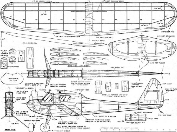
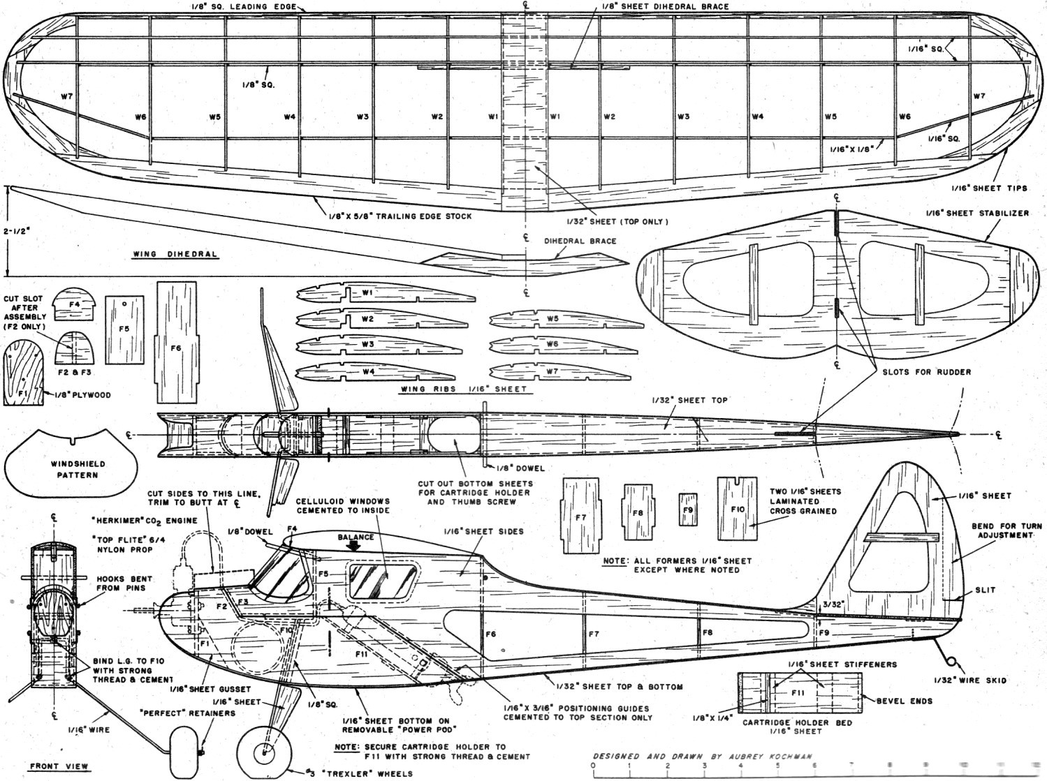
Fizz-Wizz CO2-Powered Model Airplane Plans
"Fizz-Wizz" Materials (Balsa unless otherwise noted)
Two pieces 1/16" x 4" x 36"; (1) 1/32" x 3" x 36"; (1) 1/16" x 3" x 36"; (2)
1/8" x 1/8" x 36"; (2) 1/16" x 1/16" x 36"; (1) 1/16" x 1/8" x 36"; (1) 1/8" x 5/8"
x 36" tapered trailing edge stock.
Also: 1/8" plywood; 1/8" dia. birch dowels; 1/16" dia. music wire; 1/32" dia.
music wire; 1 pr. #3 Trexler wheels; cement; clear dope; colored Jap tissue; celluloid.
Notice:
The AMA Plans Service offers a
full-size version of many of the plans show here at a very reasonable cost. They
will scale the plans any size for you. It is always best to buy printed plans because
my scanner versions often have distortions that can cause parts to fit poorly. Purchasing
plans also help to support the operation of the
Academy of Model Aeronautics - the #1
advocate for model aviation throughout the world. If the AMA no longer has this
plan on file, I will be glad to send you my higher resolution version.
Try my Scale Calculator for
Model Airplane Plans.
Posted January 15, 2024
(updated from original
post on 9/2/2013)
|