|
"The
Gloster
Meteor F Mk.8 was the last and best day fighter version of the Meteor, and equipped
the majority of home based RAF fighter squadrons in the early 1950s. The
Meteor
T Mk.7 two seat trainer had featured a longer nose, added to carry the second
crewman, which was found to improved the directional stability of the Meteor. This
longer nose was installed on late production
F
Mk.4s, but produced new problems of its own, causing unacceptably large changes
in the centre of gravity as fuel or ammunition supplies were used up. "
-- from the HistoryOfWar.org
website Meteor F Mk.8
Ducted fans fascinate many modelers, and soon there will be commercially available
fan systems. Here's one of the best aircraft for DF propulsion and a practical model
for you to build. Takes two strong 40s.
by David D. Nelson
The Gloster Meteor first flew on March 5, 1943 and was Britain's first Jet Fighter.
Meteor Mark Is took part in the final stages of the war against Germany. By 1948,
the design had pro-gressed to the F. Mark 8 and this Mark was Britain's No. 1 Fighter
for five years. It also served with many other nations well into the 1960s taking
part, for example, in the Korean war in the hands of the Royal Australian Air Force.
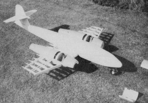
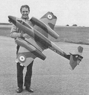 Your happy
author holding his plane illustrates that this is a big model. By the way, the real
plane also has a smooth skin since most of it was plywood covered.
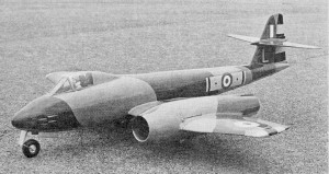 It is a
most inspiring model made up of three cylindrical shapes. Someone could easily make
these in fiberglass. Many pleasing color schemes apply to this plane.
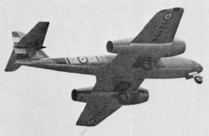 How nice
to see a jet that doesn't fake it with a propeller. The model Is a fine CL Scale
ship, but also suitable for RC-almost as is. Imagine the sound It must make-a roaring
whoosh.
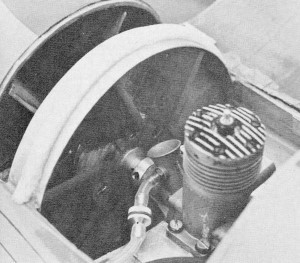 The heart
of the matter is the fan system. The author has been working with DFs for a long
time to learn how big, how many fans, what airfoils, etc. The installation is like
a pusher's.
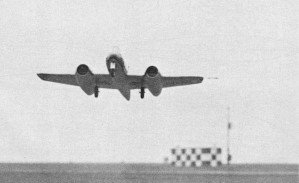 In the air.
 As it is
designed, the Meteor takes lots of careful planking around many bulkheads. The end
result is a light, strong, monocoque assembly. Wings are quite strong when sheeted.
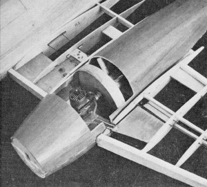
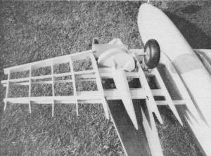 Inside surface
of duct is lightly fiberglassed for protection and smoothness. The flow straight-eners
and internal cone are essential to proper performance of the fan system. Note a
disc is used here to keep the shroud perfectly round and close fitting for the fan.
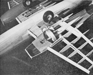 The rather
big wheels on the model are actually scale. Obviously. they produce gobs of drag.
Retracts would help perform-ance as well as the jet impression.
 Engine sits
on an aluminum plate sandwiched in a plywood mount. This must be exceptionally rigid.
Any vibrations could cause the fan to hit Its shroud with disastrous results. Note
fuel tank location in the wing.
The model presented here was scaled from original drawings kindly supplied by Hawker
Siddeley Aviation Ltd., with additional information and details from Profile Publications
No. 12 and The Gloster Meteor, a Macdonald Aircraft Monograph by Edward Shacklady.
The only deviation from scale outline con-cerns the jet pipe diameter which has
been enlarged.
Experiments carried out on a Mig 17 using restrictors in the tail pipe to cut
down the effective diameter proved that with this power unit setup 31/4 in. dia.
was the smallest allowable without en-countering a serious loss of thrust. A tail
pipe diameter which is the same as the fan would be ideal, but would rule out 99%
of possible subjects. By the same ruling, the intake area should be greater than
that of the fan. Again, this is not practical, so additional intake area must be
incorporated by providing cutouts forward of the fan covered with mesh to make them
less conspicuous.
Construction
It is assumed that only the experienced modeler will tackle a model of this type.
Although the structure is more or less conventional, a more than usual amount of
time and patience is required.
Special construction techniques described on the plans apply mainly to the nacelle
and fan construction. I am convinced that the thought of having to make a fan propulsion
is the reason most modelers are reluctant to try ducted fan propulsion. It is a
great pity because the fans are very easy to construct, and both fans plus a spare
can be completed in a couple of evenings' work. Who knows? If you persevere, you
may even come to enjoy building them. In fact, it can be fascinating to experiment
with different blade shapes, numbers of blades, pitch, etc.
Although the plans describe fan construction, it may help if the material used
for the blades is described more fully. It is a laminated, cotton fabric, phenolic
resin-based, plastic sheet called Tufnol. The grade I use is Carp brand. It is available
in the U.S., but queries about your local engineers' sources of supplies should
unearth a homegrown equivalent in other countries. Try asking for Conolite, Phenolite
or Tayloron to specifications NEMA LI 1-1965 LE.
To bend the curve into the blade, grip the short edge in a vice about 1/8". Apply
gentle pressure to the top edge. At the same time, heat the bottom half of the blade
with a butane torch keeping the flame moving back and forth at all times to avoid
blistering the material. The material will be felt to give when the heat has sufficiently
softened it. When the curve has been formed, keep the pressure on until it has cooled
slightly. Obviously, pressure can-not be applied by the bare hands and an asbestos
glove is one form of protection. Alternatively, use a piece of hardwood as a pusher
shielded on one side by a patch of metal or wood screwed on as a flame shield.
As the flame should be moving back and forth continually, the patch should not
become hot enough to scorch the wood underneath. Practice will be required before
consistency is achieved and a few blades will be blistered in the process. Persevere,
however, and it will soon become second nature. Full instructions for assembling
the fan will be found on the plan.
The nacelle construction is rather laborious, but it should be possible to make
one half shell per evening. 5and each half shell smooth and silk or nylon cover
before removing from jig. Then sand the insides smooth before applying fiberglass.
If you can dream up a quicker form of construction, remember that the nacelle adds
rigidity to the wing and, therefore, must be of reasonably rigid construction itself.
The main airframe assembly is built up around the sub-assembly of 51 and 52,
plus the main undercarriage members, bellcrank and aluminum engine mounting plates.
Add formers F6, F7 and F8 noting that these do not lie square to 51. Glue the 1
x 1/4" crutch to these formers and add the rest of the fuselage formers, taking
care that assembly is true. F1, F2 and F3 are glued to F1A, the nosewheel leg is
installed, and the complete unit added in one go. Fit one or two strips of planking
to hold assembly rigid, always checking that no distortion creeps in. Assemble fin
with bellcrank fitted, and glue in place. Note that the leading edge of the fin
includes the front outline of the bullet fairing. Fit all push rods and leadout
wires. Glue ribs R 1, R2 and R3 in position plus the 1/2 x 1/4" rear spar which
is glued to former F9.
Complete all planking. Fit ribs R4 and ply spars 53 and 54; and rib R5, then
the 1/4" sq. spars and the remaining ribs. Add 1/2 x 1/4" rear spars and the leading
edge.
Bolt motors in place with shroud ring template and shroud ring positioned. Fit
top half of nacelles, add flow straighteners, lead out tubes and balsa cone, then
fit bottom half. Use strong rubber bands to hold the two halves together while setting.
Reinforce seam inside with fiberglass tape and fill any gaps outside with balsa
and filler. Finally cover with a strip of silk or nylon. Keep a ply disc or tin
lid of suitable size wedged in the end of the tail pipe to assist in maintaining
a circular section. Remove when necessary and always replace after work is finished.
Do not discard completely until model is finished.
Fit fuel tanks and sheet wings. Add fairings and wing tip blocks. Cover with
tissue. The tail plane is the only part that can be built flat on the plan. After
sheeting and carving, the leading and trailing edges fit to fin. Connect elevator
horn, add elevators and sheet fin. Carve to section the rudders. Glue fixed portion
in place first and build up bullet fairings. Add top and bottom rudders. Offset
can be incorporated if desired. Remove hatch areas on the nacelles with a razor
saw, make fiberglass hatch cover and fit. Cut out auxiliary intake area and cover
with aluminum mesh.
The cockpit canopy was adapted from a commercial canopy cut to fit the aluminum
framed windscreen. Fit remaining details, e.g., undercarriage doors, gun covers,
tail bumper, etc. If desired, the ailerons can be cut free, reinforced and fitted
back as separate items.
All that remains is the finishing and this is up to the individual. A wide choice
of color schemes can be found in Profile Publications No. 12.
The Meteor is the fifth ducted fan model built over the last four years starting
with the Saab J21 R, following with a Mig 17, Saab Viggen and Meteor Mark 4. All
flew and the lessons learned have been used on the Meteor Mark 8. The model flies
well, but requires careful handling until flying speed is attained. Acceleration
is notoriously slow and a smooth paved takeoff area is desirable as 1 to 1/½ laps
will be required to get airborne followed by a shallow smooth climb out. Once airborne,
the model is a spectacular sight, flight is stable and shallow climbs and dives
are permissible. Always remember, however, to keep control actions smooth and gentle.
Make no mistake, this model is no rat racer or stunter. If, for example, sufficient
speed for takeoff cannot be obtained, it is possible that the model is tracking
out of the circle causing excessive drag. Cure by twisting the under-carriage legs
so that when the model is pushed from behind it travels in a straight line or even
turns slightly into the circle. The all up weight of the model should be between
12 and 13 lb. which will include about 12 oz. of lead in the nose. I cannot over
emphasize the need to use light wood only for the tail assembly; an ounce or two
saved here could save several ounces of nose weight. Any saving of weight is reflected
by an increase in performance.
Starting the engines using a pulley cord is not difficult as long as you have
a helper to hold the model on the ground firm and steady. Hold the pulley cord with
one end in each hand so that a loop is formed. Drop the bottom of the loop to fit
in the pulley groove. Turn engine over a few times to pressurize the fuel tank.
Then pull cord sharply with the left hand letting go of the cord with the right
hand at the last moment. Stand in front of the nacelle facing the rear of the model
for starting. Always use a clothes peg type clip on plug connector. Do not use the
push on type as these can come adrift and get sucked into the fan with disastrous
results. I speak from experience. See that the glow clip is secure at all times
during starting and when tuning the engine. To install engine and fan, place fan
in the shroud ring. Then put the engine in position placing fan and pulley on shaft.
Add nut and tighten up finger tight only. Bolt engine securely in place. Insert
tommy bar in pulley and tighten nut with a spanner. Always use the tommy bar to
stop the fan assembly from turning. Gripping the fan by the blades will stress and
possibly crack the blade at the root causing it to shear under running stresses.
Even if you have no intention of building this particular model, my objective
will have been achieved if your interest in ducted fan propulsion has been aroused.
Models nowadays have a tendency to become stereotyped and even scale modeling suffers
from an excess of Mustangs, Zlinns, Spitfires, Fokker DVIIs, set.
Ducted fan propulsion is not new. It has just never been fully exploited. Yet
it can open up a completely new field of experimentation and prototypes. It has
recently been proven with model helicopter design that, if a sufficient number of
people tackle the problems involved and are enthusiastic enough, wonders can be
achieved in a very short time. Maybe this could happen with ducted fan design, even
to the extent of manufacturers getting interested. The model jet aircraft is an
ideal subject for the application of foam core wings, molded fiberglass or ABS plastic
fuselages and nacelles. Perhaps one day we will be complaining about an excess of
F86 Sabres, Phantoms, etc., in Scale competition.
 <click for
larger version>
Notice:
The AMA Plans Service offers a
full-size version of many of the plans show here at a very reasonable cost. They
will scale the plans any size for you. It is always best to buy printed plans because
my scanner versions often have distortions that can cause parts to fit poorly. Purchasing
plans also help to support the operation of the
Academy of Model Aeronautics - the #1
advocate for model aviation throughout the world. If the AMA no longer has this
plan on file, I will be glad to send you my higher resolution version.
Try my Scale Calculator for
Model Airplane Plans.
Posted January 8, 2011
|