|
Website visitor Joe S. ,of the great
state of Texas, wrote asking me to post this article on the Grumman Ag-Cat biplane
crop duster. According to Joe, "In the 70's I worked for Grumman as a design engineer
located at the Schweizer Aircraft plant at the Chemung County Airport near
Elmira New York. I actually grew up in Elmira. For Grumman, I worked on the
design of the Pratt & Whitney PT6-15AG engine installation for the
G-164D Turbo Ag-Cat."
It's easy to see why he has such an interest in the airplane.
Grumman's "Ag-Cat" Proves Perfect Subject For Control Line Scale
Builders
By Paul J. Palanek
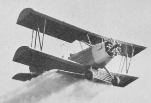 Big Ag·Cat with 450 hp engine totes
2,100·lb payloads using Swathmaster chemical dispenser made by Transland Aircraft,
Torrance, Calif. 220 hp Ag·Cat takes 1,600· pounds.
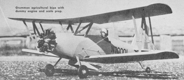
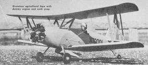 Grumman agricultural bipe with dummy
engine and scale prop.
AG·CAT BILL OF MATERIAL (Medium Grade Balsa unless otherwise
specified)
One piece 1/2" x 4" x 36" for Fuselage sides; (1) 1/4" x 2" x 36" for Fuselage
deck; (1) 1/4" x 3" x 36" for Fuselage formers; (3) 1/8" x 2" x 36" for Wing ribs,
fuselage bottom; (2) 1/4" x 1/4" x 36" for Fuselage filler strip; (3) 1/4" x 1/8"
x 36" for Wing spars; (2) 3/4" x 3/4" x 36" for Wing leading edge; (2) 1/16" x 4"
x 36" for Wing bottom; (2) 1/16 x 3" x 36" for Wing top; (2) 1/16" x 2" x 36" for
Wing top; 1" x 1-1/2" x 24" block for Wing tips; 3/8" x 5/8" x 24" Hardwood for
Engine mounts; 3/16" x 5" x 24" Plywood for Formers, bellcrank platform, gear reinforcements;
1/8" x 4" x 16" Plywood for "N" struts cabane struts; Scrap block balsa for Dummy
engine and scale prop.
Misc. items - 3" bellcrank; Acme fuel tank; wheels; 1/16" and 1/32" dia.
wire; nuts and bolts; sheet brass; solder; cement; clear and colored dopes; Silkspan;
stretch thread rigging; large Veco horn; dummy pilot; decals; .29 engine; and 9-6
Tornado prop.
Wildcat, Hellcat, Panther, Cougar, Tiger and now, the Ag-Cat crop dusting bipe by
Grumman Aircraft. Like its predecessors it is a fighter-a fighter of agricultural
pests.
From the ground up the Cat is designed for crop spraying or dusting. It incorporates
a number of unusual features. For one thing, the plane will take half a dozen different
engines in the 200 to the 450 h.p. range. The choice is left to the buyer. Upper
and lower wing panels are interchangeable along with the ailerons. Rigging is simple,
no internal and a minimum of external wiring.
Both the air speed indicator and engine tachometer are mounted on a separate
panel forward of the cockpit in the pilot's "flying line of vision". During dusting
or spraying operations pilots have little time to look inside the cockpit.
Specifications for the airplane are over-all length of 24' 8"; 35' 8" span; gross
weight 3600 lbs; empty weight 2180 lbs; 29 cu. ft. (217 gals.) hopper Volume. Hopper
load is 1000 lbs. The Ag-Cat has been designed to make a continuous 1.5-G turn at
dusting speed and at maximum gross weight.
Our model is designed around a 1" scale bringing the upper panel to a 36"full
span. The .29 power plant is housed behind a dummy 7 cylinder radial engine; with
a short nose moment all movements of control are most responsive. The model floats
in on a monostrut landing gear and a spring leaf swivel tail wheel.
Construction could begin with almost any part of the model. However, we prefer
to start with the fuselage since all members fasten to it one way or another. The
sides are 1/2" sheet balsa broken and shaped as indicated. All formers aft of the
firewall are 1/4" sheet balsa. The firewall is 3/16" plywood. A 1/4" thick disk
of sheet balsa forms the nose of your Ag-Cat. The engine is mounted prone; be certain
the 3/8" x 5/8" hardwood motor bearers are secured to the fuselage accordingly.
Fasten the 3" bellcrank to the plywood platform as indicated. Secure a 1/16"
dia. wire pushrod to the crank with the tail end extending beyond the fuselage.
The deck and nose sections are built up from 1/4" sheet balsa laminations, shaped
as in the cross sections. Prior to fastening the lower 1/8" sheet covering, fashion
the landing gear from 3/32" dia. wire as shown. Sandwich this between two sheets
of 3/32" plywood, fasten to the fuselage. At this point, place the Acme fuel tank
in position in former "B", secure with cement.
As all this is left to dry proceed with the sheet balsa tail surfaces. Both the
vertical and horizontal members are fashioned from 1/4" medium grade sheet balsa.
A large Veco horn fastens the elevator halves and these are joined to the stab with
cloth hinges. These surfaces carry a full radius on all their edges. Fasten the
stab assembly to the fuselage and the fin on top in a previously cut slot. Join
the pushrod to the Veco horn. Be certain these additions to the fuselage are cemented
well.
At his point, the lower 1/8" sheet covering is put in place. A hardwood wedge
is inserted at the tail end of the fuselage, this member carries the tail wheel
assembly. Make the necessary cutouts for cockpit, lower wing and proper fitting
of the engine. Before setting the fuselage aside, shape from 1/32" sheet brass the
dummy landing gear legs, soft-solder to the gear wire.
The wing panels are extremely simple, a minimum of structure is employed. All
ribs are 1/8" sheet balsa, the leading edge is 3/4" sq. strip; there is no trailing
edge. Start by laying out the lower sheet covering of each panel. Shape the leading
edge with the proper dihedral at each tip, cement to the lower sheet covering. When
dry, add the ribs; follow with the 1/8" sq. leading edge spars and 1/8" x 1/4" main
spars. Allow this assembly to properly dry.
With the panel sufficiently dry to work, sandpaper the ribs blending in all rough
spots also, feather edge the trailing edge to receive the upper covering. The pur-pose
of the spars is to support the upper wing covering which is 2" and 3" wide sheet
balsa with the joining seams falling on the spars. The wing tips are fashioned from
balsa block, 1" x 1-1/2", cement these in place, when dry shape to proper contour.
Having completed all structures and having brought them to proper finish and
contour, apply two coats of clear dope with a light sanding after each ap-plication.
Cover all wood surfaces with a light grade Silk-span, doping all over as you proceed.
When completed, apply a second coat of clear dope allowing to dry hard at least
ten hours. When satisfied, apply four coats of balsa sanding sealer, sanding after
each brushing. All surfaces receive three coats of Aircraft gray and two coats of
Orange yellow trim. Be certain the lower wing is fastened in place with lower sheet
covering added, then proceed. Allowing time for the above to dry, then add the plywood
cabane and "N" struts. Both are cut from three-ply plywood, take note of the grain
direction, this is important for maximum strength. Assemble the struts between the
double ribs, forcing the cabane struts into the fuselage deck. Both wings are set
at zero degree incidence. This assembly must be done with care and proper fitting.
All rigging is stretch thread, gray in color. The wind screen is .020 celluloid,
the pilot is a painted plastic dummy cemented in cockpit. The line guide is formed
from .020 music wire, cloth bind to the left wing "N" strut. Add antenna assembly,
decal numerals, cockpit liner, instrument fairing and other details now.
The drawing shows the components used in the assembly of the tail wheel. Brass
spring leaf is used for the strut with standard sheet brass for the yoke. The yoke
swivels in the strut with the spring neutralizing the action. This entire assembly
is fastened to the fuselage with two # 3 wood screws.
Our completed Ag-Cat carried a Fox 35 power plant; however, a "29" should show
excellent results - the difference in weight being of little consequence. A prop
of 9-6 proportions will provide good performance. On the field we use 75' lines
with little fear of slack. The Cat has tremendous area and, while under complete
control, in theory we almost have a free flight on our hands.
You will note
photos and plans show a hopper carried under the lower wing along with a 7 cylinder
radial engine in the nose. To add to the realism of the completed model these items
should be constructed and added. The hopper fashioned from 1/16" sheet balsa is
made a permanent fixture of the aircraft. The dummy engine is for display only.
In building, the crankcase is hollowed to fit the shaft and washer of the mounted
engine. The scale prop is fastened to the engine with a modeler's pin. For the radial,
balsa is used throughout. Thread is wrapped around the cylinders to simulate fins.
Crankcase and rocker boxes are painted grey, pushrod and cylinders are black. Remember,
the dummy engine is removed for flights.
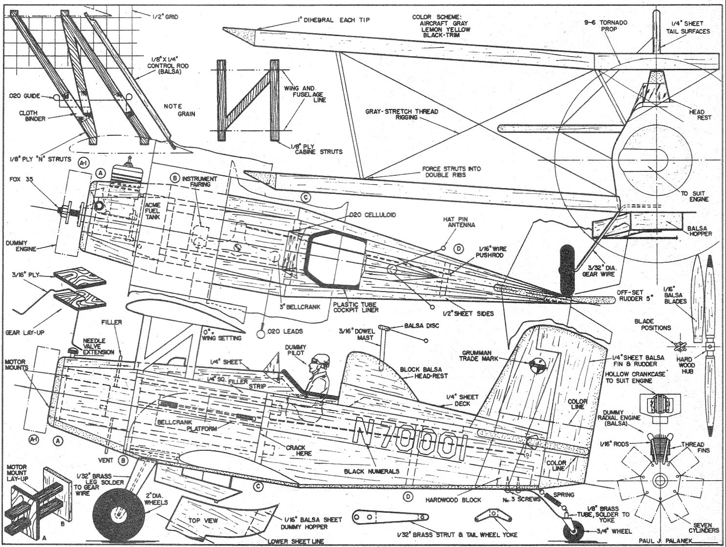
Full size working drawings for the Grumman Ag·Cat are part of Group Plan
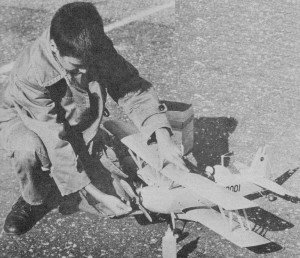
#461 from Hobby Helpers, 1543 Stillwell Avenue, New York 61, N. Y. (S5c). At right
young Ronnie Palanek, 12, prepares his Dad's model for flight. Dummy engine has
been removed and flying prop substituted for scale exhibition airscrew.
Grumman Ag-Cat Plans Sheet 1
<click
for larger version>
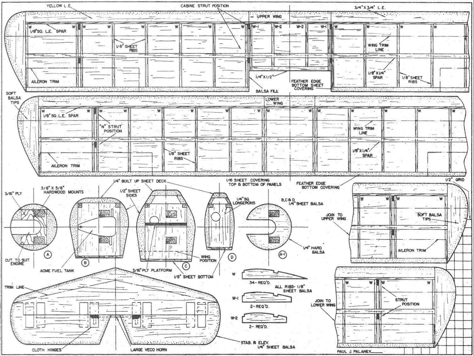
Grumman Ag-Cat Plans Sheet 2
<click
for larger version>
Notice:
The AMA Plans Service offers a
full-size version of many of the plans show here at a very reasonable cost. They
will scale the plans any size for you. It is always best to buy printed plans because
my scanner versions often have distortions that can cause parts to fit poorly. Purchasing
plans also help to support the operation of the
Academy of Model Aeronautics - the #1
advocate for model aviation throughout the world. If the AMA no longer has this
plan on file, I will be glad to send you my higher resolution version.
Try my Scale Calculator for
Model Airplane Plans.
Posted 8/4/2012
|