|
It's hard to imagine back when
only 14 years had passed - to the month - since the Japanese surrendered to the
U.S., that this article with plans for a control line Kawasaki Ki-61 Tony model
was written in the August 1959 edition of American Modeler magazine. The
Imperial Japanese Air Force, like the German Air Force (Luftwaffe), was made up
of highly skilled pilots and increasingly capable aircraft. The Japanese were a
notable more terrorizing enemy since many were willing to sacrifice their lives
in battle, whereas the Germans were more of the mindset of living to fight another
day. It is now 52 years hence since this article was written and very few of the
men who fought WWII - on all sides - are still alive to bear witness to the action.
As long as there are people who want to dominate the world, there will be wars.
Today, it's militant Islam that wants everyone to submit to Sharia law. The difference
with this fight is that political correctness prevents us from winning by conjuring
"rules of engagement" that are more likely to get our soldiers killed than the enemy's.
All of the lawmakers should be required to fight on the front lines for a month
under the rules they impose on the troops.
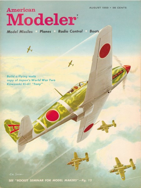
Kawasaki Ki-61 "Tony"

Kawasaki Ki-61 Tony
Slick World War Two Control Line Scaled 3/4 Inch to Foot
by Walter A. Musciano
The only Japanese single seat fighter to be powered with an inline liquid cooled
engine during World War II was the Kawasaki Ki-61. This plane was used by the Japanese
army virtually throughout the war in New Guinea, Rabaul, China and Philippines and
over Japan intercepting B-29 bombers. The Ki-61 is generally considered to be the
Japanese Army's counterpart of the Japanese Navy's vaunted "Zero." The U.S. recognition
nickname for the Kawasaki Ki-61 was "Tony."
The 3,120 "Tony" fighters that saw service were powered by a twelve cylinder,
Vee type engine of 1175 horsepower, designed Ha-40. This was undoubtedly a German
design built in Japan under license. In fact, the entire treatment of cowling and
exhaust stacks gives "Tony" a typical German rather than a Japanese appearance.
Maximum speed was 348 mph with a gross weight of 7650 lbs. The craft could climb
to 16,400 feet in seven minutes. Armament consisted of two 20 mm cannon mounted
in the wings outside of the propeller arc and two heavy calibre machine guns buried
in the cowl. This was one of the few Japanese planes that was well armored.
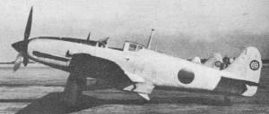
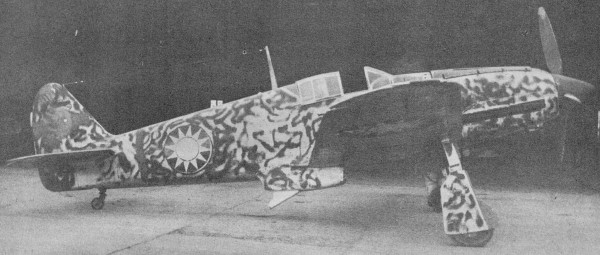
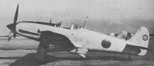
Sporting Chinese insignia, Jap Tony (upper left) like one above
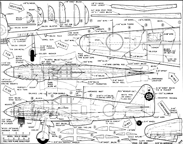
shows influence of Germans. Full size plans for constructing a Ki-61 model are available
on Group Plan #859 from Hobby Helpers, 770 Hunts' Point Ave., New York 59, N. Y.
(85c). When ordering specify plan number desired, rather than name of model.
An air cooled engine version was also produced in limited numbers during the
closing years of the war. This was the Ki-100. Reports indicate that the Kawasaki
Ki-100 could meet U.S. "Mustangs" on equal terms and the better pilot usually won.
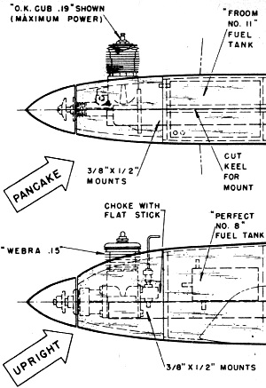
"Tony" is beautifully proportioned for control line sport flying and this 3/4"
to the foot scale model can be powered by a glow plug or diesel engine from .09
to .19 cubic inch displacement. Standard two line control system is shown; however,
the Stanzel Mono-line control system can be installed if desired. The clean, uncluttered
lines and absence of struts or rigging makes this "Tony" a pleasure to own and fly.
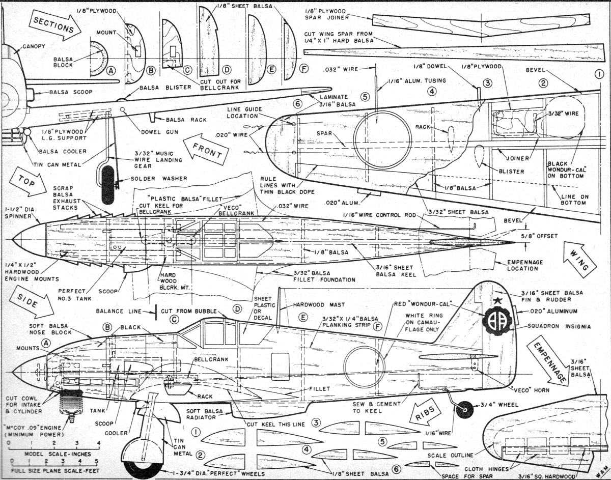
As is customary with our vertical keel fuselage construction, the wing is built
first. Begin by cutting the spar and ribs to shape and cementing these together.
The 3/32" sheet lower covering should be assembled to form the correct chord distance
from standard 3" balsa sheets. When the covering has been assembled and cut to shape
it can be cemented to the bottom of the ribs and spar. Start with the spar and work
the covering towards the leading and trailing edges of the ribs. Use plenty of cement
and hold the covering in place with pins until the cement is dry.
Bend the wire landing gear struts to shape being certain to make one left- and
one right-hand strut. Sandwich the upper portion of the struts between two rectangles
of plywood. Drill small holes and firmly "sew" this assembly together. Use plenty
of cement. When dry, the landing gear is cemented to the wing spar, ribs and lower
covering. This is done by passing the strut, from above, through the lower covering
in the exact location that· the strut emerges at the bottom. Do not spare the cement
in installing the landing gear. Several applications are recommended.
The 3/32" sheet balsa wing upper covering is installed in the same manner as
the lower. Before this is attached, however, be sure to bevel the leading and trailing
edges of the lower covering to match the contour of the ribs' upper camber.
Sheet balsa wing tips are laminated of 3/16" sheet balsa and cemented in place.
Entire wing should be sanded thoroughly at this time with 3/0 sandpaper.
Cut the body keel to shape and cement it to the wing. Be certain to cut openings
in the keel for the fuel tank, and bell-crank movement. Cut the bulkheads and formers
to shape and cement these to each side of the keel. Install the engine mounts to
the bulkheads using plenty of cement.
The elevator and stabilizer are cut to shape, sanded to a streamline section,
and hinged together after the control horn has been firmly installed. Cement the
stabilizer into the slot in the keel.
A hardwood block serves as the bellcrank mount. Attach the lead-out lines to
the bellcrank and then bolt the bellcrank to the mount. Slip the control rod onto
the horn and bellcrank and then cement the mount very securely to the top of the
wing. It will be necessary to make a small hole in the wing covering to accommodate
the nut.
Install your "commercial" fuel tank at this time. This must be rigidly wedged
in place.
The fuselage is planked with 3/32" x 14" balsa strips. These should be carefully
fitted and cemented to the fuselage formers as well as to each other. Hold in place
with pins until cement dries. Small hairline spaces between the planking strips
caused by improper fitting can be easily filled with "Plastic Balsa." When the planking
is complete the nose block should be installed. Install the engine mounting nuts
and bolts tightly. Apply plenty of cement around the nuts to hold them in place.
Carve the nose block roughly to shape and then split it apart along the horizontal
centerline. Hollow the interior to clear the engine mounts; and then cement the
nose to the fuselage. Complete the nose and sand the entire fuselage thoroughly.
Cement the wing fillet sheet balsa foundation to the wing and fuselage. When
dry apply several layers of "Plas-tic Balsa" with the fingers to form the fillet.
Make the fillet slightly oversized to allow for sandpapering when the "Plas-tic
Balsa" is dry.
The fin and rudder should be cemented in place.
Carve the radiator from soft balsa and sand smooth. Cement this to the fuselage
belly and form fillets with "Plastic Balsa."
The windows forward of the cockpit and the rear vision panels behind the cockpit
are cut out and covered with sheet plastic. The planking should be cut away about
1/32" all around the opening. This cut must be to a depth equal to the thickness
of the plastic sheet. Carefully cut the plastic to 1/32" larger than the opening
and cement it in place.
Seal any rough edges or imperfections around this installation with "Plastic
Balsa." Sand smooth. Those modelers who are not interested in these details can
use black or blue decal sheet for the windows and this can be applied after the
model has been painted.
At least six coats of Balsa Filler should be liberally applied. Sand each coat
when it is thoroughly dry. Up to twenty coats can be applied for a super finish.
The Kawasaki can be colored all light gray with black anti-glare panel forward
of the cockpit, or it can be colored all bright green or bright green with splotches
of yellow and a hazy blue bottom. The red ball insignia is outlined with a white
band only when the plane is camouflaged.
The splotches of yellow on the green are made by cutting yellow "Wondurcal" decals
into small irregular pieces and applying them onto the finished model. These will
adhere tenaciously and are fuel proof.
The cockpit canopy can be cut from a standard bubble. many of which are available
at most hobby shops. This should be installed now. Other miscellaneous details such
as exhaust stacks, radio mast, tin can metal wheel covers, and wheels are added.
Carefully cut a hatch in the cowl in order to install the engine. Loosen the
mounting bolts gently in order not to the nuts that were previously cemented to
the mount. Openings for the cylinder and needle valve are cut in the nose. The entire
cowl interior should be well protected with several coats of fuel proof dope. Install
the engine and attach the cowl hatch with a few drops of fuel proof cement.
The model should balance at the point shown. Lead weights, firmly attached to
the inside of the nose or tail, should be used to remedy any unbalanced condi-tion.
In view of the relatively small wheels it is advisable to fly your "Tony" from
a paved area or grassless packed earth. Flight lines thirty to fifty feet long can
be used for flying this model. The prototype airplane was flown with a three bladed
propeller.
Kawasaki List of Material
Material is Balsa except where otherwise noted.
Three 3/32" x 3" x 36" for wing covering; (1) 1/8" x 3" x 36" for wing ribs,
fuselage formers; (1) 3/16" x 3" x 36" for tail surfaces, wing tips; keel; (1) 1/4"
x 1" x 36" for spar; (15) 3/32" x 1/4" x 36" for fuselage planking; (1) 1/8" x 6"
x 12" plywood for wing Joiner, bulkheads, landing gear supports; (1) 1/4" x 1/2"
x 12" hardwood for engine mounts; (1) 3/32" dia. x 18" music wire for landing gear;
(1) 1/16" dia. x 24" music wire for control rod, tall wheel strut; (1) 3" x 3" x
3" for cowl, radiator, scoop; (1) Berkeley Canopy; 8 oz. Aero Gloss Balsa Filler
Coat; 4 oz. Aero Gloss Swift White dope; 1 oz. Aero Gloss Jet Black dope; one sheet
red Wondurcal decal.
Miscellaneous - Straight pins; "3/0 dry sandpaper; 6/0 and 8/0 sandpaper; brass
washers; Aero Gloss Plastic Balsa; one tube Ambroid Cement; small jar clear fuel
proofer to protect canopy; aluminum spinner.
Color note - add the black dope to tile whit. a little at a time until a pearl
grey is obtained - use the remaining black for the landing gear struts and the anti-glare
panel forward of the cockpit.
<click for larger version>
|