|
Just as with model helicopters,
there was a time not so very long ago (relative to the age of the Earth, anyway)
that if you wanted a ducted fan propulsion unit for your model jet aircraft, you
had to design and build it yourself. As usual, the pioneers of the hobby took the
figurative arrows for those of us who would follow in their painfully forged path.
Renowned British aeromodeler P.E. Norman wrote a series of three articles for
American Modeler in 1962 detailing his method of building ducted fan models
- including the ducted fan itself. This third and last installment includes plans
for a semi-scale Rapier jet fighter. There are few people today who would undertake
to build the ducted fan unit from scratch since much more powerful, efficient products
are available today, but there are some lessons to be learned by reading the history
of ducted fan development.
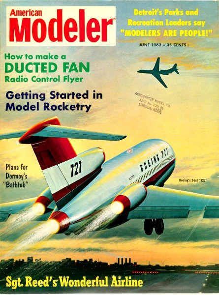
How to Make a Ducted Fan Radio Control Flyer
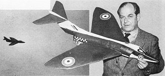
P.E. Norman, outstanding scale and radio plane designer brings
you his ducted fan "Rapier." PE's D/F has a great list of contest wins and exhibition
flights to its credit. For additional details on ''PE'' and his remarkable radio/ducted
fan job, see
February
1962 and
March
1962 issues of American Modeler. Mr. Norman painted the cover drawing for that
February issue ... it depicts the "Rapier" plane presented here in plan form.
By P.E. Norman
This 34" span swept wing ducted fan aircraft, although not an actual scale model
is the culmination of a number of years development in ducted fan machines and is
designed for the Cox Olympic, Fox 15 or K&B 15.
I have built two of these machines, both radio controlled and their performances
are truly impressive. I have not flown them free flight, but with the elimination
of the radio gear weight, I would guarantee the performance to be terrific with
any of the above engines.
The models are immensely strong, and have on numerous occasions stuck into the
grass or ground up to their intakes (when the rudder has jammed due to a wrong signal)
without the slightest damage, much to the amazement of spectators and fellow modelers.
The all-up weight with radio in each case when new is 38-oz. Therefore as free flight
models it would be 32 to 34-oz.
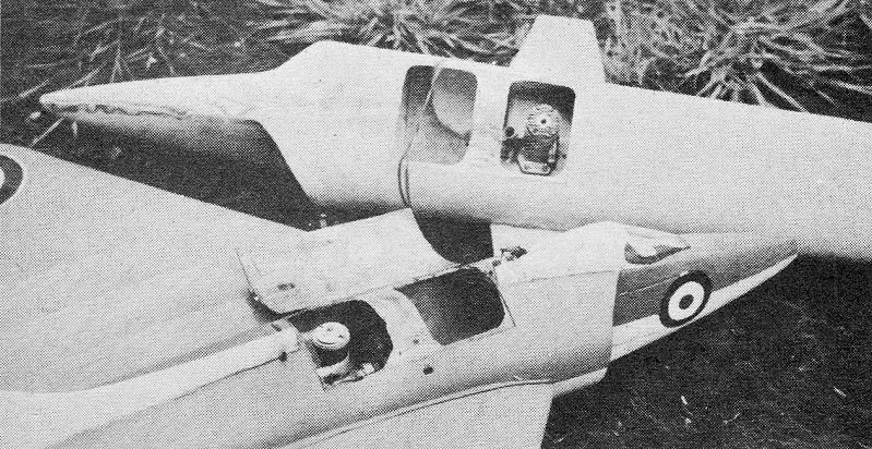
My models are finished in two color schemes - grey blue upper surfaces, white
undersurfaces - British red, white and blue roundels. These colors look very attractive
in the air, besides serving the useful purpose of helping one to see which direction
the machine is turning when under radio control.
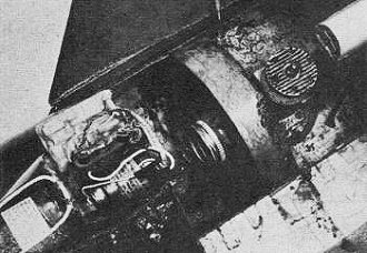
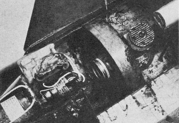
Ducted fan unit details.
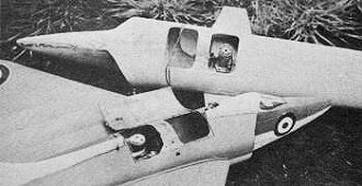
Ducted fans in P.E. Norman's Rapier models.
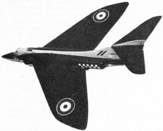
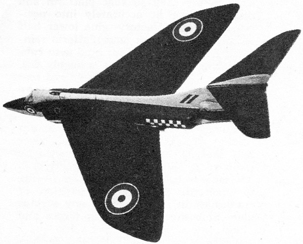
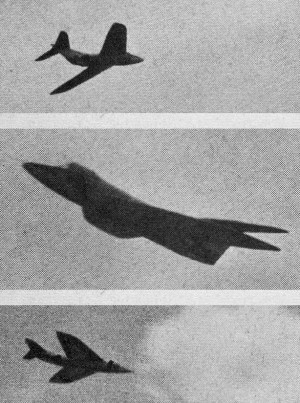
P.E. Norman's Rapier ducted fan job in flight.
Here are the building instructions for making one of these models. The sequence
of operations appear in the order in which it is best to tackle construction.
1. Engine mount/wing tongue platform. Mark the shape accurately on a piece of
resin-bonded 5-plywood 1/4" thick. Also the necessary cut away shapes on the center
line to accommodate the particular engine to be used, and the fuel tank. With a
scroll saw, cut out the platform and drill engine mounting bolt holes. Also drill
hole for fuel line from tank.
Cut two small tin plates and drill for engine bolt holes. Screw bolts through
these tin plates and up through ply platform. Lock bolts by soldering to tin plates.
File and sandpaper to streamlined shape inner portions of platform between engine
and inside of duct. Cut the two reinforcing pieces from medium balsa and carefully
cut the slots in each to fit platform. Do not glue yet. Make streamline cone behind
tank from either balsa or cork and drawing paper and thoroughly dope and fuel proof
inside and out. Cut aluminum or dural saddle which passes under crankshaft case
and fasten securely in position on ply platform with No. 3-48 nuts and bolts.
Check engine and tank position and bolt engine temporarily in position. Cement
streamline tailcone in position. Cut the hardboard disk; drill center to be snug
fit in engine crankshaft, and file and sandpaper circumference to as true a circle
as possible. This circle must be made accurately as its purpose is to ensure that
the engine and mount are accurately placed in the duct.
Cut a 1" wide strip of 1/32" 3-ply wood-grain running the length of the strip
- and carefully wrap round circumference of hardboard disk, mark the overlap position
accurately and glue (resin glue). Bind temporarily to hold till dry. (When dry,
remove binding.)
Mount hardboard disk onto engine shaft and push plywood ring onto disk. Mark
the positions where the ring touches the edge of ply platform, and make two saw
cuts about 1/8" deep in platform, for the edge of the ring to fit into.
Remove disk and ring from engine and build up oval section to ring with soft
balsa wood glued to outer sides of ring with resin glue; hold in position with rubber
bands till dry. Carve balsa wood away carefully till necessary shape is obtained,
carving the inside parts each side of ply ring to a knife edge.
2. The Fan. This type of fan, which is the result of several years experiment,
is extremely efficient and not too difficult to make, although accuracy is the key
note. Make the blade pitch-cutting jig as shown in sketch. The hub of 9-ply wood
may be turned on a lathe or, failing this, an octagon should be marked out carefully
on the piece of 9-plywood. The center drilled to take the crankshaft of the engine
to be used.
Cut the octagon out with a hacksaw. Now with file and sandpaper smooth edges
off the octagon until true circular shape is obtained. Fasten jig to hub, place
both lightly in vise and carefully cut blade slots with hacksaw. Cut blades from
1/32" thick fibre to the length indicated.
File the edges off and sandpaper to streamlined section and curve section into
blades by finger coaxing. Fasten blades into hub with resin glue, then drive a 3/8"
shoe brad through the hub into each blade.
Mount fan onto the fan disk with suitable nut and bolt, and trim off each blade
to about 1/32" under diameter of disk. Remove fan from disk and thoroughly dope
and fuel proof. Replace disk and ring onto engine and platform. Make starter pulley
from fuel can cap or as alternative method as shown in sketch.

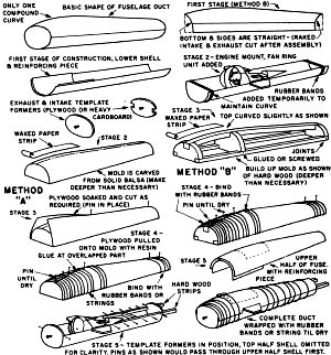
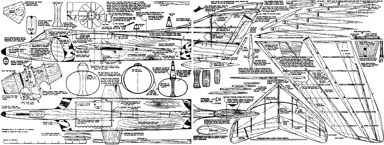
Rapier ducted fan fuselage duct construction

Rapier ducted fan blade fabrication.
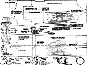
Rapier plywood plan patterns.
This completes the power plant for the model.
3. Lower half of Fuselage/Duct. The fuselage/duct is constructed entirely from
1/32" 3-ply wood, formed in two halves, top and bottom. As can be seen from the
drawing, the lines are kept quite straight, except for the one curve on the upper
forward part of the fuselage. Select resin bonded 1/32" 3-ply wood of a good quality
for the fuselage.
Cut lower half fuselage to size and pattern shown, with grain running lengthwise.
(It will be found that the plywood can easily bend across the grain but not in the
length of the grain.)
Mark center line inside and outside of plywood. Cut reinforcing piece of 1/32"
plywood which extends from front end to just beyond ring position in lower half.
Glue this into position inside lower half with resin glue holding in place with
paper clip or clothes pegs and slip rubber bands over all to give temporary curvature
to lower shell. Allow to set.
Measure position of platform edge exactly on ring and disk. Place ring and disk
in position on 3 ply half and mark off platform position accurately. Cut slots in
ply shell so that platform and disk and ring fit accurately into position. When
satisfactory, glue lower half of ring and platform, and platform reinforcing pieces
in position; bind with rubber bands and wait until thoroughly dry. Place rubber
bands round front and rear end of shell to help maintain curvature till set. Cut
intake and exhaust former templates from heavy cardboard.
Make and fit metal tie rods from underside of platform to inside of lower half
shell. The engine will have to be removed to do this operation, but it is advisable
to leave disk in position in ring to maintain dead central position of crankshaft
in ring. Remove any surplus glue. Smooth off reinforcing pieces and pieces around
ring into duct sides.
4. Mold for upper half fuselage/duct shell. This may be made in two different
ways as shown in sketches.
A. Carve the complete upper shape of fuselage from a block of hard balsa, allowing
about an inch deeper than the actual depth required. Ensure that the front section,
section of fan and rear section, are accurate. Sandpaper to smooth finish and cover
front portion with wax paper-held in position with Cellophane tape. This is to prevent
plywood shell from sticking to this portion of mold when gluing.
B. (2nd method) Make silhouette shape of fuselage top half from 1" thick hardwood
or hard balsa. Cut front section - section at fan position, and rear section from
1/2" hard balsa or hardwood. Cut two bottom strips from 1/2" x 1/2" hard balsa or
hardwood. Glue the whole together firmly. Cover upper front portion where curve
occurs with wax paper, held with Cellophane tape.
5. Forming the upper half shell of fuselage by shaped mold method.
A. Cut the resin bonded 1/32" to pattern shown (this is oversize to allow trimming
to shape when forming is completed). Mark center longitudinal line on both sides
with pencil. Cut center line with sharp knife back to point indicated.
B. Soak ply in hot water and lay centrally on the mold. Drive pin through ply
into mold at center rear end and just beyond end of central cut in ply. Wrap this
portion with rubber band or string to hold to mold.
C. Have resin bonded glue ready.
D. Put glue on the upper surface of one of the ply alongside the central slit.
E. With rubber bands or tape, firmly bind the slit portion of ply onto mold,
letting one side pass over the other, and starting at the middle end (fan position)
of the slit. Bind tightly and closely until the other end is reached and fasten
off binding securely. Drive in a pin or two if necessary to help hold overlapping
portions in position.
Try to get the wood as even and free from lumps as possible, but do not be unduly
worried if they do occur, because this portion will be reinforced from the inside
and in any case the finished joint is filed and sandpapered and eventually covered
completely by the cockpit shape and spine.
This operation is really not as difficult as it may sound, provided the wood
has been soaked before hand. Allow to dry absolutely thoroughly.
Remove binding and carefully remove from mold. The shell will open out but this
does not matter as it will be formed again finally during the assembly of the upper
and lower halves.
Cut the front reinforcing piece of plywood. Glue with resin glue to inside of
shell and hold in position by placing shell back on mold and bind or pin the front
half as before.
While setting, mark the exact position of the engine access hatch, and make a
small pin hole through each corner to transfer position of hatch to inside of shell.
When dry remove reinforced shell from mold. The hatch may be partly cut through
at this stage but must not be entirely removed from shell until assembly of the
two halves has been completed.
More data on full size plans.
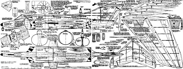
P.E. Norman's Rapier Ducted Fan
Rapier Plans
<click for larger version>
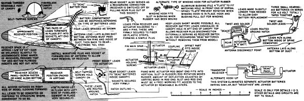
P.E. Norman's Rapier Ducted Fan Rapier Radio Equipment Installation
<click
for larger version>
Notice:
The AMA Plans Service offers a
full-size version of many of the plans show here at a very reasonable cost. They
will scale the plans any size for you. It is always best to buy printed plans because
my scanner versions often have distortions that can cause parts to fit poorly. Purchasing
plans also help to support the operation of the
Academy of Model Aeronautics - the #1
advocate for model aviation throughout the world. If the AMA no longer has this
plan on file, I will be glad to send you my higher resolution version.
Try my Scale Calculator for
Model Airplane Plans.
Posted November 20, 2023
(updated from original
post on 5/17/2014)
|