|
Airplanes and Rockets visitor Dave
J. wrote to ask that I post this article on the Missy DARA (Dayton Air Racing Association
) quarter midget racer that appeared in the April 1974 edition of American Aircraft
Modeler magazine. It is a scale knockoff of the full-scale Miss Dara Formula racer.
I offer to do this for people at no charge as time permits. Also, I usually post
a scan of the plans, but if you are going to build the model, I highly recommend
buying a set from the AMA Plans Service
if they are still available. Missy Dara plans do not appear to be available at this
time. The AMA will scale the plans to any size you need, so you're not locked into
the original wingspan. House of Balsa manufactured a
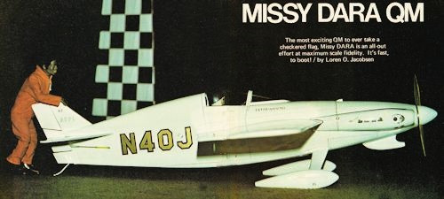
Miss Dara kit back in the 1980s. Missy DARA QM
 The most exciting QM to ever take a checkered
flag, Missy DARA is an all-out effort at maximum scale fidelity. It's fast, to boot! The most exciting QM to ever take a checkered
flag, Missy DARA is an all-out effort at maximum scale fidelity. It's fast, to boot!
By Loren O. Jacobsen
The original full-size Miss DARA was a Formula racer of the mid 1960s. After
several attempts at competing, however, it suffered a fatal crash in a test flight
and never appeared on the race scene again. I couldn't resist trying to recapture
its appealing, unique shape in the form of a Quarter Midget (QM) racer.
It is my impression that many modelers buy modeling magazines for the inspiration
from the photos of other modelers' efforts. Besides the information that can be
gleaned from the articles, pictures of fellow modelers' planes inspire daydreams
of the perfect flying model. Missy DARA was designed to race, but she should also
inspire other QM enthusiasts to build racers which are more representative of their
full-scale counterparts.
According to the rules, QMs should be "semi-scale or recognizable replicas" of
aircraft that have raced in one way or another. Maybe the rules should say "easily
recognizable," because, as the competition gets faster, the racers become less recognizable.
Extremely dis-tasteful to me is the kit practice of supplying a mass-produced fuselage
of minimum dimensions, along with a variety of canopies and flying surface tip designs.
The simple fuselage form, not resembling any full-size aircraft, is used merely
to attach two or three features of the airplane it supposedly models. Whatever happened
to the "Builder of the Model" pride cultivated by transforming either a drawing
or a well-engineered kit into a good looking, recognizable airplane? I am not advocating
super-scale, detailed QM racers - only more scale effect.
The 7/8" wing rule makes way for more scale wing planforms, which Missy DARA
has. Fuselages built to the five-in. minimum depth, however, are hard pressed to
capture the spirit of the racers after which they are modeled, So I chose to maintain
the unique outline of the Miss DARA; despite the fuselage depth. I also decided
to retain the low aspect ratio and outline of the Miss DARA wing. You can see that
Missy DARA is not a scaled down Formula I racer, but was built to be a QM. But!
Can a racer with a deeper, more scale outline fuselage be competitive? Missy DARA,
though over six in. deep, answers YES!

Stripped down for routine maintenance, the model Is a myriad
of necessary hatches. All systems can be safety checked in a matter of minutes.

The wing is pre-MonoKoted, except for the gluing area. The canopy
assembly will be permanently affixed later. It's nice to build in this modular fashion,
since the components may be easily handled all the way through the finishing stages.

Jenesco fueling system hidden under the cowl keeps nitro uncontaminated.

The first prototype Missy DARA used a modified K&B Schnuerle.
The backplate and rotor were rotated 1800 for more efficient location of the carb
(better breathing makes for faster running), Linkage conversion is a snap

Tucked away nicely is the Schnuerle. It just sits there, saying,
"I'm gonna get ya!"
The accompanying photos (for inspiration, remember) show her with a scale fin and
rudder outline. She was flown many times this way, but she proved to be a wayward
girl in the tight scatter pylon turn. The plans show her with a larger vertical
fin, which proved to be the answer to keeping this little cutie in the groove.
Two other changes have been made to the model since the photos were taken. Competition
in the North Central Pylon League (NCPL) here in the Minneapolis-St. Paul area,
has become so fierce that I found I could afford neither the luxury of a sub-rudder
and steerable tail skid, nor the large cheek cowls.
I found that Missy DARA could be raced without rudder control. Takeoffs are quite
straight because of the right thrust in the engine mounting. I taped the rudder
in place and eliminated the servo and linkage. The plans show an optional movable
rudder.
Also shown on the plan are smaller, more scale cheek cowls, intended to present
a more streamlined front end. Note in the photos that Missy DARA originally had
a rear rotor engine installation utilizing the left cheek cowl as the intake for
the carburetor. Also, only the simpler front rotor engine installation, which is
easily maintained and allows more room for an uncramped fuel tank area, is shown
on the plan. I believe that most model builders are innovators by nature and will
make construction changes to suit their building techniques and engines.
For innovators who want to use rear rotor engines, I would suggest incorporating
hardwood beam mounts, and allowing for fuel tank access from the radio compartment
through F-2. Or you may want to move F-1 back, and use the long Tatone mount. I
have included a photo of the rear rotor K&B 15 Schnuerle engine, which has had
the backplate and rotor rotated 1800, in order to bring the carburetor around to
the left cheek cowl. Linkage from throttle arm to exhaust baffle was made from nylon
rod and two short lengths of 2-56 threaded rod. If you use this engine set-up, the
left cowl will have to be removable.
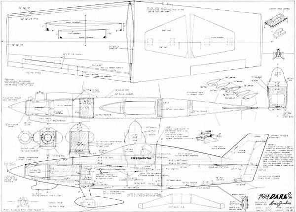
The strength of this design is in the one-piece unit of wing and fuselage. The
wing can be built in two halves, and finished separately with Super MonoKote before
joining. The lower half of the fuselage is constructed over the plan top view. The
upper half of the fuselage is shaped from blocks of balsa, with the portion over
the wing separating to allow for wing attachment. All parts of the fuselage can
be painted and detailed before cementing the wing in place.
Construction
Wing: Cut the foam wing cores ac-cording to the templates shown
on the plan. Be sure to make right and left cores and mark them as such. The cores
will actually be oversize in planform, so that the leftover foam cradles can be
used later as support for the leading and trailing edges during sheeting. Using
a straightedge and sharp razor, cut LE and TE of cores per plan. Cut the front edge
of the Sig 1/4 x 2" aileron stock to plan. This piece will closely match the taper
of the core, and is epoxied in place. Epoxy 1/4" sq. LE spar to core and sand to
airfoil shape. Locate the aileron torque rod positions and make slots for them.
Cut sheeting with razor and straightedge and butt glue together, allowing extra
sheeting over the core edges. Note that there is a 5/8" overlap of sheeting at the
TE. Sheet the bottom of the wings and cut the aileron sections out of the cores.
Use rubber cement for balsa to foam joints and epoxy for balsa to balsa. Do not
overlap these cements, and be sure to allow the solvents to evaporate from the rubber
cement for at least 15 min. before attaching the sheeting. Epoxy the torque tube
assemblies in place, raising them in their slots so that the centerlines are 1/32"
above wing chord lines. Now sheet the top of the wings and trim excess sheeting
to the core edges. Don't remove the entire 5/8" trailing edge. Add the 1/4" sq.
LE and tips, and sand to shape. Cut the ailerons from 1-1/4" TE stock and locate
the hinges and the holes for torque rods. Groove the ailerons so that the rods will
lay flush in their front edges. I finished the wing halves at this point with Super
MonoKote.
Join the wing halves with epoxy, using each respective cradle as a dihedral jig.
Block up the tips so that the top of the wing is straight and the bottom offers
a small amount of dihedral. This will not be a strong joint, but will hold until
the wing is fitted to the fuselage.
Fuselage: Again, using a straightedge and a sharp blade, trim
two sheets of 1/8 x 3 x 36" balsa, so that two edges are parallel and cut to the
side view shown on the plan. Cut the 1/16" balsa doubler to outline and sand the
front edge of the RIGHT doubler 1/32" shorter so that when F-1 is positioned, it
will give right thrust to the engine mount. Mark the wing cutout areas on the fuselage
sides, but .do not cut them out yet. Accurately mark the wing chord lines on the
fuselage, so that the LE is 3/32" above the TE in relation to the thrust line. Cut
the slot for the stabilizer to the positive angle shown. Mark cheek cowl outlines
so that you will not cut or sand into these flat areas. Epoxy or contact cement
the doublers to the sides. The sheeting can be blocked up during doubler attachment
to provide a slight inward curve. Bevel the rear inside edges to the fuse sides.
Cut F-4 from a flat piece of 3/8" balsa sheet to plan top view, and mark the
centerline and the former locations. Pin F-4 down over top view and tack glue F-2
in place. Glue on F-3 and the fuselage sides, taping the rears together. Pull the
front together to a 13/4" inside measurement and secure with tape. Push a couple
of pins through the rear fuselage on the rudder hinge line. Angle these to aid in
fitting the scrap balsa block for hinging optional rudder and holding skid wire.
Bend the 1/16" wire tail skid and sandwich between the ply pieces. Epoxy it in
place flush with the fuselage bottom. Glue in the 1/8" sq. balsa corner longerons,
and add 1/8" sheet bottom. Epoxy the 1/4" ply bottom servo hatch mount at F-3. Fit
the 1/16" ply hatch mounting screw bases at F-3 and secure the landing gear mount.
Then accurately cut 1/16" balsa sheets to fit between the pieces of ply and the
fuselage sides. Glue the 1/2" sheet bottom to these parts without getting glue on
the fuselage sides. Drill for No.4 screws. The hatch will hold the fuselage sides
in position when the wing is mounted.
Attach the Kraft-Hayes No. 19-B mount to F-1 for a Supertigre installation, or
adjust F-1 to the desired engine and mount. Epoxy in place, checking the thrust
offset. Epoxy the 1/16" ply triplers between F-1 and F-2, and fill the corners of
the tank area with 1/2" triangular stock. Glue the 1/4" balsa nose doublers in place,
and add the 1/2" bottom nose block. Fill all the corners of the engine area with
scrape balsa. Cut out the right side of the fuselage until the engine is easily
inserted into the mount. Now, with the prop and spinner on the engine, adjust the
location of the nose ring and cement in place. The bottom fuel tank hatch is shaped
from 1 x 3" balsa block and can be hollowed for the battery pack, if it will fit
here.
The lower fuselage is now a solid unit and can be turned over. Cut F-5, F-6,
F-7, 2 x 2" turtle deck block and canopy block to their approximate outlines. Tack
glue all of these in place and rough shape with a spokeshave and sanding block.
When the basic shape is achieved, remove the blocks, hollow, and add desired cockpit
detail. Cut F-4 and F-5 apart at the separation line at the rear of the cockpit.
Glue all blocks back into place, but don't glue the separation joints. Attach canopy
and add the 1/32" balsa fill to each side of it. Mask off the canopy for protection
and finish shaping and sanding the fuselage.
Cut out the wing slots marked on each side of the fuselage and lift out the section
above the wing location. Sand the wing openings until the wing can be easily slipped
into place, inserting TE first. A force fit can twist the fuselage out of shape.
Now, with wing in position, check alignment of stabilizer and vertical fin, and
glue them to fuselage.
If you will be painting the wing and the fuselage together, cement in the wing
now and add check cowls and fil-lets. If finishing fuselage separately, proceed
now without wing in place. Leave flat cowl areas unfinished for a good glue bond.
When you finish painting the fuselage, cement in the wing and top section and attach
cowls. Be sure to epoxy 1/32" ply braces across wing center joint after wing is
set in fuselage.
Landing gear: The landing gear (LG) struts were cut from a 1/16" thick aluminum
blank. Although a one-piece unit would be best, I cut mine in two pieces from a
Sig blank. File the LE and TE of the struts round and rubber cement 1/32" sheet
balsa to top and bottom sides. Lightly sand the balsa to a streamlined shape and
cover them with wide vinyl tape. Presto! A streamlined LG that is no thicker than
1/8" wire.
Wheel Pants: Missy DARA looks stark naked without her wheel
pants on, so make the extra effort to give her some neatly shaped wheel coverings.
The pants shown on the plan are trouble free on black-top landing strips. If you
fly from a grass field, you might try larger wheels and move the pants a little
forward on the struts. The inside 1/16" ply piece fits around the edge of the strut
and is the key to keeping the pan, in place. Adjust the width of the center balsa
section to the wheels you in end to use. The epoxy bead around the edges of the
wheel wells allow the pants to be sanded very thin if desired. The balsa fill around
the ply pieces ill make the sanding job easier.
Canopy and Cockpit: Part of the character of Missy DARA is in
the shape of her canopy. If you don't want to mold one, you can still maintain her
beautiful curves by carving a balsa canopy and painting it. Since you have to carve
one in either case, to get the proper shape, you may as well use it for a mold.
Sig's .015 heat forming plastic works well for the canopy. Use a piece of 1/4"
ply, large enough to allow a firm grip, for pressing the hot plastic over the mold.
Cut a hole in the center to the top view shape of the canopy, making it 1/8" oversize.
Attach plastic to the plywood with wood screws and two strips of wood on the bottom
side. Drill two holes part way into the bottom of the balsa mold for 1/4" dowels
and mount them in a firm base, such as a length of 2 x 4". Clamp the 2 x 4" to your
beautiful dining table or a Sherman tank, or whatever you can find around the house
to hold it. Preheat the oven to 425°, and put the plastic in the oven, setting it
across a cake pan or the like so that the soft plastic won't touch the oven shelves.
Now, wearing gloves, snatch the plastic from the oven and press down, with a quick,
firm action, over balsa mold. The trick is to do it fast, without doing it crooked.
The balsa canopy mold does not have to be coated with anything to fill the pores.
Sand it with the grain to lay down the nap.
The two-in. Williams Bros. racing pilot had its head twisted to the left by holding
a hot soldering iron close to its neck. Its shoulders must be trimmed to get it
into the cockpit.
Finishing: The full-size Miss DARA was canary yellow with blue
racing numbers, but somehow all my models end up white. Choose your colors and favorite
finishing method.
I finished the wings with Super MonoKote. The fuselage was done with surfacing
resin and auto enamel. The trim and racing numbers are from MonoKote trim sheets.
The fillets were made with white General Electric brand silicon rubber. I have seen
other colors, but they are not as easily available. This material can be smoothed
with a finger dipped in alcohol, but cannot be re-worked much. Practice on scrap
first.
<click image for larger version>
Notice:
The AMA Plans Service offers a
full-size version of many of the plans show here at a very reasonable cost. They
will scale the plans any size for you. It is always best to buy printed plans because
my scanner versions often have distortions that can cause parts to fit poorly. Purchasing
plans also help to support the operation of the
Academy of Model Aeronautics - the #1
advocate for model aviation throughout the world. If the AMA no longer has this
plan on file, I will be glad to send you my higher resolution version.
Try my Scale Calculator for
Model Airplane Plans.
Posted February 7, 2024
(updated from original
post on 1/7/2012)
|