|
A lot of careful thought and detail
went into planning and rationalizing why a biplane version of the venerable MO-1
control line Carrier model should fly better than the traditional monoplane platform.
It was January of 1973 when this article appeared in American Aircraft
Modeler magazine. Time has shown that the old adage about if something isn't broken,
don't fix it must ring true here. That is not to say efforts should not be undertaken
to improve on a design, just that in this case going to a biplane configuration
was not the answer. Maybe website visitor Duke J., who wrote to ask for this article,
can pick up where Mr. Gerber and Mr. Higley (yes, THE Harry Higley) left off. Maybe
a MO-Tripe...? Mo-BipeRequirements for Profile Carrier allow non-scale
designs.
 A biplane can offer several advantages such as reduced weight and frontal area. A biplane can offer several advantages such as reduced weight and frontal area.
Don Gerber and Harry Higley
During
the 1920s Martin made the MO-1 monoplane which was used as the subject for both
a Class I and Class II Navy Carrier ship. The Class I version appeared in the August
1969 issue of American Aircraft Modeler. The subject of this article was designed
for the Profile Navy Carrier event, and its name was not chosen because Martin made
a biplane variant of the MO-1 - they didn't. It was chosen because the Bipe retains
many of the construction features and the same general appearance of the MO-1.
In an era when the Scale Navy Carrier events were dominated by Guardians; the
MO-1 was a most unlikely but highly successful choice for the event. The real airplane
was to be a battleship based observation plane in the early 1920s. Only two ever
saw Carrier service; an old letter reveals they were not regarded as fit for this
service by the Navy. The MO-Bipe may appear an unlikely choice for Profile Carrier,
but for a different reason. Most fliers do not normally think of a biplane for a
Speed event.
Due to the nature of the rules, the biplane configuration, however unlikely it
may seem, offers the very decided advantage of reduced weight and frontal area.
A monoplane with a 36-in. span would require about an 8.5 in. chord to achieve the
300 sq. in. required by the rules. A few airfoil sketches will show that the minimum
thickness that will maintain the structural integrity of a built-up wing is about
0.75 in. This gives a frontal area of about 27 sq. in. A wing this large does not
lend itself well to solid construction. The MO-Bipe used two solid, easy to
shape wings with a 28 in. span, 5.7 in. chord and 0.25 in. thickness. These give
a total frontal area of 14 + sq. in., or only slightly more than half that of the
monoplane. The Bipe will also have a shorter fuselage because of the reduced wing
chord. This 15 to 25 percent overall reduction in fuselage dimensions will provide
a substantial weight reduction. One last advantage for the biplane is the capability
of using full span strip ailerons on the lower wing which eliminates the need for
tip weight, thus saving another ounce. Strip ailerons are easier to install than
conventionally placed ailerons, as there is no need for long torque rods or clumsy
pushrods. The importance of the working ailerons and rudder cannot be over-emphasized.
This plane was designed from the ground up for Profile Carrier, but the full potential
of the design cannot be realized unless the moveable ailerons and rudder are used.
Unusual construction features shared by the MO-1 and MO-Bipe include solid wings
and easy to install semi-enclosed controls. Another common feature is variable sweep
line leadouts. The less the lines sweep back, the faster the plane will go. However,
the plane will be more likely to come in. By trying different holes in the tip guide,
the most favorable line sweep may be found.
Full credit for the design belongs to Don Gerber. Don and I correspond regularly
and this spring he sent some photos of the MO-Bipe and asked if I would be interested
in a joint article, as he did not want to devote the large block of time that assembling
an article such as this requires.
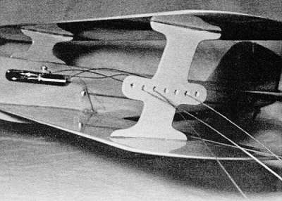
 All painting was done with linkages removed.
This is also handy when crashes make major adjustments necessary.
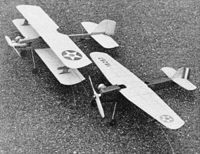
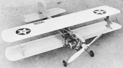
The MO-Bipe with its predecessor the MO-1, both in pre-WWII markings. Only the
MO-1 has scale heritage.
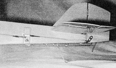
Adjustable leadouts provide for windy or calm conditions. Moved forward line
tension is less but speed is higher.
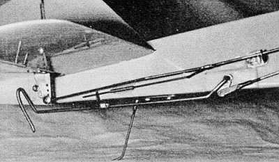
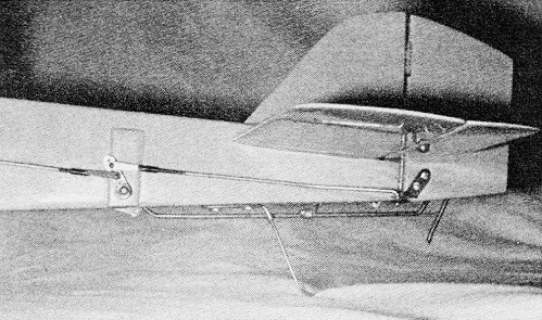
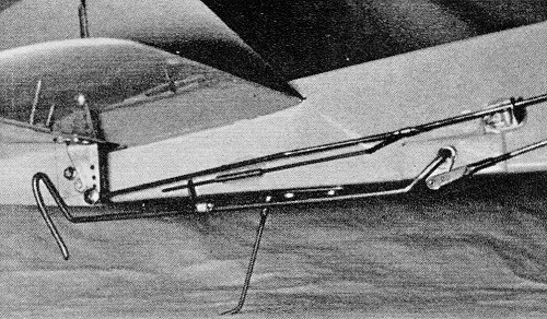
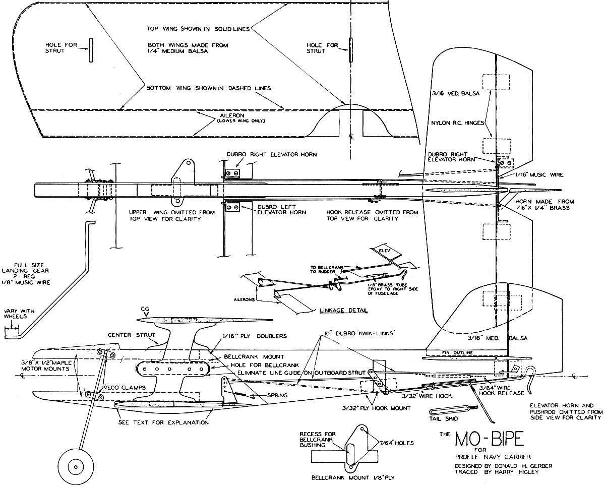
Plans show the hook-drop, elevator and aileron systems graphically. Note use
of adjustable clevises throughout.
Construction
The construction procedure was planned to avoid two problems. First, a completely
assembled biplane is difficult to finish due to the limited space between the two
wings. Second, painting after the controls are installed at best will look bad because
of partially painted rods and other components; worse yet, the paint may foul the
whole system. The strategy employed is to assemble the plane minus the upper wing
and struts. The controls are then temporarily installed, checked, adjusted and then
removed prior to finishing. The main frame, control surfaces, struts and upper wing
are finished separately, and then the whole model is permanently assembled.
To begin with, cut all plywood parts. These include the bellcrank, hook and tail
skid mounts, the struts and the plywood fuselage doublers. The doublers should be
cut a little oversize as they may not end up in exactly the position they should.
The resulting slight overhang is easily trimmed and sanded flush with the fuselage.
Drill the required holes in the bellcrank mount, inboard strut, and tail skid mount.
Now is as good a time as any to bend the landing gear, tail skid and hook. Attach
the wheels with soldered washers. Attach the tail skid to its mount with No. 6 x
3/8" sheet metal screws. This will facilitate easy removal of the skid for painting
and replacement, though the latter will probably never be necessary.
The bellcrank on the J. Roberts unit must be shortened. Notice on this control
unit that there are, in addition to the holes provided for "the leadouts, two dents
indicating alternate leadout positions. Drill at these points, then trim the excess
from the bellcrank. Attach the leadout wires. I personally prefer Perfect brand
- they are a little stiff, but are strong and solder well. Mount the control unit
to the bellcrank mount to verify that the moveable bushing that is recessed into
the mount has adequate clearance. Once this is established, remove the control system.
The next operation is fabricating the fuselage. Cut the motor mounts to the correct
length. It will hurt nothing to drill 1/4" holes in them from the landing gear mount
back; it will save some weight. Glue the bellcrank mount to the upper motor mount.
Cut the fuselage from 1/2" sheet balsa. Choose this piece of wood carefully as a
heavy sheet adds nothing but weight. Cut all slots including the bellcrank hole,
except the one for the lower wing which will be cut after the doublers are installed.
Cut the recesses for the hook mounts and the tail skid mount, and glue these in
place. Glue the motor mounts in position. Notice on the plans that there is a piece
of 1/2" wood on the top of the upper mount. Cut this from a scrap and glue it in
place. The doublers may be attached with contact cement or Titebond. If the latter
is used, clamp between blocks, remove any excess glue with a wet rag, and allow
to dry overnight.
After the fuselage assembly dries, it is convenient to drill holes for the motor,
tank, hook and landing gear. If a drill press is used, it will be necessary to hold
the fuselage on the block of wood so that the bellcrank mount clears the table.
Trim the excess from the fuselage doublers and sand these even with fuselage.
Now the slot for the lower wing may be sawed. Hold the fuselage on a couple of
blocks so the bellcrank mount clears the jigsaw table. The slot should be 1/4" and
not the shape of the airfoil. The lower wing is left with a rectangular cross section
where it intersects the fuselage. There are two reasons for this. First, it is difficult
to cut a hole that will mate well with the airfoil. Second, sliding the fuselage
onto the wing would surely nick and gouge the wing if the slot was a snug fit. Attach
the landing gear.
The wings are made from 1/4 x 6" medium sheet balsa and are no more difficult
to shape than a wing for a hand launched glider. Draw parallel lines on the top
and bottom of each wing 1.75" from the leading edge and 2.5" from the trailing edge.
Also draw lines down the middle of the leading and trailing edge of the wing blank.
Sanding the airfoil should be done on a smooth surface. Any glue glob will chew
up the under-surface of the wing. This sanding is done with a 3 x 12" block with
60 grit paper glued on one side and 220 grit on the other.
The lines that are drawn on the wing blanks are used as guides to shape the airfoil.
As one looks down on the wing, the wood above a plane determined by the line on
the leading edge and the forward line on the top of the wing is removed by sanding.
The airfoil is shaped by removing these wedge-shaped sections. The center section
of the bottom wing is left unsanded where it intersects the fuselage. Rough sand
the airfoil by using cross grain strokes with the rough side of the sanding block.
Do not sand below the guide lines and leave a 1/16" radius on the leading and trailing
edges. Use spanwise strokes with the 60 grit paper to even out any ripples. Now
remove any sanding marks with the 220 grit side of the block. Cut the ailerons from
the lower wing; then cut the hinge slots and glue the lower wing into the fuselage.
The tail assembly is straightforward. Cut, shape and slot these surfaces for
the hinges, then glue the fin and the stab to the fuselage.
Efforts have been made to keep the hardware standard, but there are three pieces
that must be homemade. These are the two horns on the hook and the horn on the rudder.
The hook horns are made from 1/16 x 1/4" brass, available from any good hobby shop.
This heavy a piece is used so there is adequate contact with the hook to insure
a strong solder joint. Solder the right horn to the hook, but leave the left one
unsoldered until after the final assembly. The rudder horn can be made from the
same material or a lighter gauge. A homemade rudder horn is necessary as a conventional
horn will interfere with the elevator travel. Attach all horns to their respective
control surfaces. Install the control surfaces but do not glue the nylon hinges
in place, as the control surfaces are removed for finishing.
Mount the bellcrank; bend and install the pushrod. Now epoxy the hook release
guide tube to the fuselage. Bend the hook release wire, then bind and solder it
to the pushrod. The aileron and rudder push rods are made from 12" Du-Bro "Kwik-Links."
Insert the hook into the fuselage. It will probably be necessary to use one or two
between the hook horns and the fuselage for spacing. Slide the horn on the left
side of the hook, bend the Kwik-Links and temporarily install them. Solder the catch
on the hook. It should disengage the release wire with about 15 to 20 degrees down.
Mount the motor and tank and bend the throttle push rod to length. The engine we
recommend is the plain bearing Fox 36 RC. This motor is as good as any other and
is by far the easiest to install. The throttle arm is in the right place and moves
in the right direction (i.e., closes the throttle when moved forward) to permit
a straight, short pushrod between the bellcrank and the throttle. It may be necessary
to make a long throttle arm to slow down the closing action. The Fox has a very
fast throttle. Other engines may require some arrangement to get the push rod around
the tank and perhaps a link to reverse the pushrod direction. This is the kind of
trouble that a new Carrier flier would be well advised to avoid.
At this point, the plane is completely assembled except for the upper wing and
the struts. Check to see that all the controls function properly. The left aileron
will not work properly because the horn on the hook is not yet soldered. It can,
however, at least be verified that the pushrods are the correct length. Remove all
the controls, the motor, tank and landing gear; the model is now ready to finish.
I suppose every flier has his favorite finishing technique. Plain dope is probably
adequate, but an epoxy finish will hold up longer when high nitro fuels are used.
The method I use is as follows: Fill any nicks with vinyl spackling compound.
Sand the entire model smooth with 320 or 400 grit paper. Brush on two coats of clear
dope and sand smooth with 320 paper after each. Apply three brushed coats of dope
and talc filler and sand with 320 after each. Next, spray a very, very thin coat
of DuPont No. 30 auto primer. This can be thinned with dope thinner. Sand this lightly.
Now spray on colored epoxy. The primer is necessary as the epoxy will not adhere
well to dope. Elaborate spraying equipment is not needed. The PreVal sprayer coats
a dollar and one unit will paint a model the size of the Bipe. The epoxy should
be applied hot. Heat it in very hot water for half an hour before application -
this will greatly speed the drying and thereby reduce the chance of dust adhering
to the finish. Reinstall the motor tank, controls and landing gear, and glue on
the struts and upper wing.
The lines and handle are critical parts of the control system, and no matter
how careful a job has been done up to this point, the lines must be cut to the correct
length or only frustration will result. The lines must be cut so that the distance
from the center of the fuselage to the center of the grip is between 60 and 60.5
ft. First, cut the elevation lines so they satisfy your feel of level. Next, hold
the handle in a horizontal position so they satisfy your fell of level. Next, hold
the handle in a horizontal position so the elevation lines run parallel all the
way to the plane. The motor is now in its high speed position. Now with the trigger
pulled back, tie the throttle line so that it sags slightly more than the elevation
lines. Slightly more means "as little as possible without sagging less." Next before
the line ends are soldered, check to see that the system has a full range of throttle
movement. Lines that are not the correct length in relation to one another are the
biggest cause of trouble to a beginning Carrier flier. Minor adjustments in length
can be made by using different size line clips.
Flying
The model is now ready to fly. If this is your first Carrier ship, it would be
wise to contact an experienced Carrier flier, let him watch you fly and then offer
you his suggestions. Carrier does not require great flying skill and endless hours
of practice. The rules for Profile Carrier are very restrictive in an attempt to
keep the event simple. It is safe to say that if the engine is well broken in and
the control system is carefully adjusted, the Bipe will keep up with the best. If
you would like to send any comments or suggestions, please send them to me at 433
Arquilla Dr., Glenwood, 111., or to Don at 1119 Parkside Dr. N., Wyomissing, Pa.,
19610.

MO Biplane Plans
<click for larger version>
Notice:
The AMA Plans Service offers a
full-size version of many of the plans show here at a very reasonable cost. They
will scale the plans any size for you. It is always best to buy printed plans because
my scanner versions often have distortions that can cause parts to fit poorly. Purchasing
plans also help to support the operation of the
Academy of Model Aeronautics - the #1
advocate for model aviation throughout the world. If the AMA no longer has this
plan on file, I will be glad to send you my higher resolution version.
Try my Scale Calculator for
Model Airplane Plans.
Posted April 24, 2023
(updated from original post
on 12/11/2012)
|