prop combination - make this a truly great stunt design." Great care
in planning was used to obtain a model that was lightweight and would fly
relatively slowly on 70-foot, 0.015" diameter (low drag) steel lines. Its 56" wingspan
and Super-Tigre .35 BB engine with a 50-oz. flying weight on 70' lines reportedly
results in a near-perfect stunter.A Precision Aerobatic Airplane - The PA-6
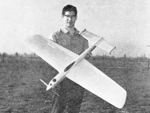
Sleek is the word! Displayed by its designer, PA-6 shows compactly
cowled nose, flowed-in canopy, and smooth surface of sheeted wing.
Cleverly blended design factors - notably engine/prop combination - make this
a truly great stunt design.
Bob Baron
My first thought in designing this plane was to use the maximum allowable line length
of 70 ft. and to take advantage of the lower drag of .015 lines for engines of 40
and below displacement. Together with a flying speed below 60 mph, the apparent
(angular) speed would be quite slow. The important trim parameters - leadout sweep,
center of gravity, tip weight, and handle width - were to be made easily adjustable
on the field to facilitate trimming.

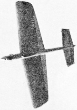
Rounding an outside loop. Ship has moderate, but very steady
pull through all its maneuvers and nearly constant airspeed.
Several features were incorporated to reduce the physical effort of flying to
the minimum. The wing was to be very rigid and to hold its airfoil, which led to
an all sheet wing. Ease of maintenance and everyday handling were considered desirable
assets. Most important, the prop (10-4) would be of relatively low pitch so as not
to stall under loads, and the corresponding high rpm would use most of the available
horsepower of our present engines.
The resulting 50-oz. ship flies at 54 mph on 70-ft. lines and can be flown through
every corner with no tendency to yaw or roll. The pull is moderate but very steady
throughout the maneuvers. The flying speed is very nearly constant due to the low-pitch
prop not stalling, as does the traditional 10-6. In the wind the low pitch tends
to brake the plane. This minimizes the vicious whipping tendency that gives stunt
flyers the jitters. A balanced elevator, together with a proper CG, handle, and
control setup, reduces the physical effort at the handle, over a conventional arrangement.
The sheet wing (13.5 oz.) weighs less than the equivalent cap-stripped D-tube.
A table of weights is provided so the builder can guide himself toward a finished
weight of no more than 50 oz. Extruded nylon bearings were used in the hinges to
eliminate a frequent trouble spot. A fiberglass cowling and strong front end minimize
the usual deterioration of the nose. This plane has a useful life of around 2,000
flights, after which most flyers would be quite tired of it anyway.
The tank is readily removable, since when permanently installed, it will no doubt
leak due to "Murphy's Law." Aluminum plates in the bearers keep them from crushing
with age. The finish was dope, filled and colored, followed by epoxy paint. The
epoxy paint has amazing resistance to fuel, and frequently the author takes ten
straight flights without bothering to clean the ship. A stooge takes care of the
dirty work, as no one would launch a plane that filthy.
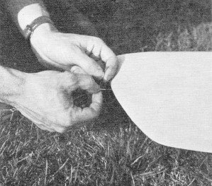
Provision of extra leadout bushings permits fine adjustments.
Play line rake and tip weight until ship does not yaw on sharp corners.
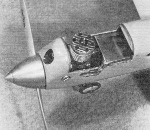
Engine-tank compartment given two coats fiberglass resin. Tank
removable. Super Tigre 35 combat engine permits 15,000 on 10-4.
The choice of wood is vital if the weight is to be kept below 50 oz. Wood of
five- to seven-pound density will give the weights listed on the table. Wood ordered
directly from Sig with a request for medium-soft will be adequate. The solid flap
and empennage are actually lighter than a built up surface, since the finish weighs
more over an open surface than a closed one. Glue is the real culprit in the weight
department. For curiosity, weigh all the ribs in a stunt wing, then hollow them
and check again. It's hardly worth the effort.
Building can be greatly speeded by assembling all components (wing, tail, fuselage)
as completely as possible separately. The fuselage in particular is built quickly
by tack-gluing the blocks and sanding everything to shape without the wing, tail,
and tank vents being in the way. After this is done, the blocks and underwing cut-outs
are removed and the wing, tail, and gear can be installed leaving relatively little
construction to be done.
The wing planking is spliced chord-wise as shown for a specific reason. The three
pieces as shown make it possible to glue the planking with little danger of it popping
up after the job is completed. First glue the trailing edge sheet and leading edge
stringer with the spar in place, but not glued. Before the glue sets thoroughly,
steam the wing as straight as possible. When you are satisfied with the alignment,
glue the main spar. Install controls and continue with the center piece. After each
sheet is in place smear each rib with glue where it meets the planking to prevent
the sheet from separating from the ribs. Do not substitute 1/16 sheet for the 3/32
planking, as it makes the job too critical. Do all sanding with a block to prevent
sagging between the ribs. Sand only enough to smooth the seams. The inboard tip
sanded and hollowed should weigh .75 ounce and outboard one should weight 1.00 ounce.
The fixed tip weight is .50 ounce giving .75 ounce of tip weight to start. The additional
.25 to .50 ounce needed is put in the tube as determined by test flights.
Table of Weights
13.5 Wing unfinished ready to install complete with
all controls and tip weight
3.0* Tail assembly including controls and rudders
2.0 Tank
0.75 Three 1 7/8" diameter Williams Bros. Scale wheels
2.0 Veco 2" spinner
8.5 Super-Tiqre .35 BB
0.5 Prop
8.0 Fuselage completely sanded with blocks
left solid with all formers and mounts installed
2.0 Assembly of components and installation
of controls, fillets
0.5 Fiber-glass cowling
8.0 Finish from bare wood
Total -- 48.75
oz.
Finish:
0.5 Two thinned clear on bare wood
2.5 Paper covering + three thinned clear
3.0 One coat of given mixture
2.0 Two coats of Hobbypoxy color
Total -- 8.0 oz.
*1/2 oz. too heavy here means 1 1/2, ounces of nose weight!
It is imperative that epoxy glue be used for the engine bearer-doubler, nose
gear mount-bearer, wing-fuselage, and main gear-fuselage joints, as well as all
horn and hinge mount installations, if the airplane is to last for a reasonable
time. The entire engine-tank compartment must be given two coats of fiber-glass
resin directly over the bare wood.
The finish was two thinned coats of clear on the bare wood, covered with Silkspan,
three thinned coats of clear. Then spray on one coat of a mixture of equal Volumes
of clear, thinner, talcum powder, and color. This last step should add no more than
three ounces when sanded properly, yet will fill all the grain. Finish the ritual
with two coats of Hobbypoxy color applied with an airbrush, not a gun.
A few words are in order on the engine. The usual plain-bearing stunt engine
has neither the power nor strength to run repeatedly at the 15,000 rpms required
by the 10-4 prop. The Super Tigre 35 BB combat mill, model G21/35, with restrictor
installed, shows no tendency to overheat at the high rpms and low airspeed of this
design. In addition, it is operating comfortably below its maximum output on a very
mild fuel of 75% methanol and 25% castor oil. No shaft extension is used, as this
is only a source of additional vibration.
Props must be carefully balanced to prevent excessive wear on both engine and
plane. The Tigre starts very quickly when hot, whereas many stunt engines simply
will not start until they have cooled. This characteristic makes it possible to
fly seven patterns an hour when practicing hard for a meet. This engine is particularly
nasty when new, but after a gallon of fuel is run through in five-minute periods
on a 10-4 it becomes relatively docile.
Proper trimming is essential to the success of any stunter. Our CG is very near
the aerodynamic center of the wing which means that inertial and not aerodynamic
forces are those principally overcome to initiate a maneuver. My handle is 2.5 inches
in line width with the control system shown and the lines are .015 x 70 ft. as measured
from center-of-plane to center-of-handle. It is very strongly suggested that the
CG and control system be used exactly as shown and that individual preferences in
feel be adjusted with handle line width only.
First determine if the engine runs exactly the same speed in both directions.
If the outsides are faster than the insides, or inverted flight is faster than right
side up, the tank is high and the engine must be raised with washers. Next establish
the engine setting that gives 55 mph on a Rev-Up 10-4 prop.
Steam the wing until line tension is exactly the same right side up as inverted.
Do not adjust this tension by bending the flaps. If the ship loses tension on insides
but not outsides, then there is more tension inverted and the wing should be steamed
accordingly. If tension is lost equally in both directions on loops, try additional
tip weight and if that doesn't help, put in additional line sweep. Play with tip
weight and line rake until the ship does not yaw on a sharp comer. The actual rake
angle agrees very closely with the theoretical calculations of William Netzeband
as published in the Sept./Oct. 1966 issue of American Aircraft Modeler.
I think you will find this ship equal to the competition, and also a pleasure
for everyday flying.
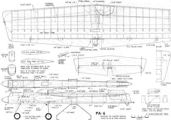
PA-6 Plans
<click for larger version>
Notice:
The AMA Plans Service offers a
full-size version of many of the plans show here at a very reasonable cost. They
will scale the plans any size for you. It is always best to buy printed plans because
my scanner versions often have distortions that can cause parts to fit poorly. Purchasing
plans also help to support the operation of the
Academy of Model Aeronautics - the #1
advocate for model aviation throughout the world. If the AMA no longer has this
plan on file, I will be glad to send you my higher resolution version.
Try my Scale Calculator for
Model Airplane Plans.
Posted February 16, 2022
(updated from original post on 8/19/2012)