May 1967 Electronics World
 [ Table of Contents] People
old and young enjoy waxing nostalgic about and learning some of the history of early
electronics. Electronics World was published from May 1959 through December 1971.
As time permits, I will be glad to scan articles for you. All copyrights
(if any) are hereby acknowledged.
The first thing I learned (or
re-learned) in reading this article is that in 1967, "Hertz" had only recently been
assigned as the official unit of frequency. According to Wikipedia, International
Electrotechnical Commission (IEC) adopted it in in 1930, but it wasn't until 1960
that it was adopted by the General Conference on Weights and Measures (CGPM) (Conférence
Générale des Poids et Mesures). Hertz replace cycles per second (cps).
The next thing that happened was that I was reminded of how images such as the
op-art tracing of antenna oscillation that are routinely generated today by sophisticated
software, required huge amounts of setup time and trials to yield just a single
useful and meaningful image using actual hardware.
The third thing was, wow, 1967 was 56 years ago, and that was nine years after
I was born. Ouch.
Radio Measurements in Space
 By Joseph H. Wujek, Jr. By Joseph H. Wujek, Jr.
Scheduled for an early launch is a satellite to be used for radio astronomy
purposes only. An array of space antennas having 750-foot elements will be used.
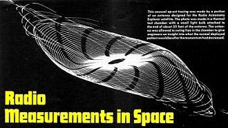
This unusual op-art tracing was made by a portion of an antenna designed for
the Radio Astronomy Explorer satellite. The photo was made in a thermal test chamber
with a small light bulb attached to the end of about 35 feet of the antenna. The
antenna was allowed to swing free in the chamber to give engineers an insight into
what the normal deployed pattern would be after the momentum had decreased.
When the brilliant Scots physicist James Clerk-Maxwell (1831-1879) published
his classic "A Treatise on Electricity and Magnetism" in 1873, very little was known
about the nature of electromagnetic (EM) radiation. Although Maxwell predicted the
existence of EM waves, it was not until after 1885 that high-frequency EM waves
were generated in the laboratory. Heinrich Hertz (1857-1894) is generally acknowledged
to be the first to generate these waves and was recently honored by having the unit
of frequency - "hertz" - named for him. The theoretical work of Maxwell and the
subsequent experimental research of Hertz thus paved the way for the technology
which we now know as radio. We use the term "radio" here to include that region
of the EM spectrum which extends from a few hertz to the edge of the infrared region,
which is about 1000 gigahertz (1 million megahertz or 1 terahertz ).
With the development of radio communications in the twentieth century, major
emphasis was placed on gaining a better understanding of the nature of radio propagation
and noise. Measurements of radio propagation and noise characteristics were, and
continue to be, made with international cooperation. The National Bureau of Standards
(NBS) of the U.S. Department of Commerce guides this effort in the United States
with technical coordination maintained among NBS, other government agencies, universities,
and industry.
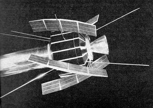
Scale model of the Radio Astronomy Explorer satellite, world's
first satellite devoted exclusively to radio astronomy.
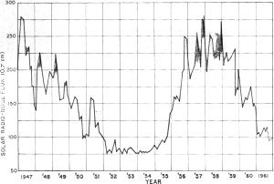
Fig. 1 - Graph of noise from solar activity at 2.8 GHz showing
the last complete eleven-year cycle. Right now solar activity is on upswing and
new peak should occur around 1969.
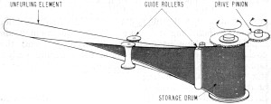
Fig. 2 - The STEM (Storable Tubular Extendable Member) principle.
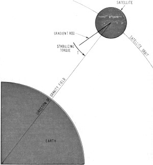
Fig. 3 - The principles of gravity gradient stabilization.
A natural outgrowth of propagation and noise studies was the detection of radio-frequency
noise from deep space. Until the recent advancements in space technology, measurement
of space r.f, signals was confined to the ground or to those altitudes accessible
to aircraft. This was, of course, also true of r.f. propagation studies. While ground-based
and aircraft measurements have contributed much to our understanding of these phenomena,
measurements from space vehicles enhance these results. Since the earth's atmosphere
acts to severely attenuate certain r.f, frequencies, a measurement of r.f. signal
strength taken above the atmosphere provides added information regarding the source,
strength, and character of these signals.
The science of radio astronomy has also benefited from space r.f. measurements.
It has been known for some time that stars, galaxies, and some planets emanate EM
waves. The star nearest earth, our sun, exhibits increased flare, or sunspot activity,
on a somewhat regular basis. In particular, the occurrence of these flares increases
to a maximum every eleven years (Fig. 1). Radio communications in certain frequency
bands are severely affected during such increased solar activity.
By studying the nature of the r.f. emanations of the sun and other stars, scientists
are able to better understand the energy processes which occur in these bodies.
The solar flares, which are believed to be reactions similar to those of a fusion
or hydrogen bomb, release enormous amounts of energy. Swarms of charged particles
and EM waves are discharged from these reactions. The earth is about 93 million
miles or 8 light-minutes from the sun, yet some of these particles and waves find
their way through the atmosphere and ultimately reach the earth. In an earlier article
("Radiation Measurements in Space", August 1966) we showed how energetic particles
are detected and measured. Here we will discuss systems used to measure r.f. energy
in space.
Space Radiometry
Instruments used to measure radiation in the EM spectrum are called "radiometers".
Many different kinds of radiometers exist; the type used will depend on the portion
of the spectrum to be measured. In this article we shall be concerned only with
radio-frequency systems.
Radiometers have been used in space experiments from the very beginnings of space
exploration. These systems generally consist of an antenna, an amplifier, and a
telemetry readout system. The amplifiers are usually of the frequency-selective
variety so as to amplify and pass only those frequencies of interest, while all
other frequencies are rejected. Some systems use several amplifiers and/or antennas
which are shared by means of automatic switching controlled by a programmer subsystem.
Ground commands may also be used to select a particular channel when the payload
is traversing a given region of space.
As in the case of ground-based systems, antenna design depends on the range of
signal frequencies to be gathered. Space radiometers have been developed which have
input sensitivities as low as 0.1 microvolt per meter. For some perspective, remember
that in order to obtain a good-quality TV picture on most commercial receivers,
a signal strength of 100 microvolts per meter is required with a signal-to-noise
ratio of at least 30 dB. Space systems can yield higher sensitivities because they
are far removed from high-level man-made signals and interference. These higher
sensitivities cannot, in general, be verified experimentally in the laboratory due
to the high level of surrounding interference.
Radio Astronomy Explorer Satellites
The first Radio Astronomy Explorer (RAE) satellite has been tentatively scheduled
for launch this year. This will mark the first time a satellite has been designed
and developed for radio astronomy purposes exclusively. Due to be another first
in space technology is the array of antennas, each of which is 750 feet in length.
These antennas were first developed by The de Havilland Aircraft of Canada, Limited.
In addition to functioning as antennas, the long tubular sections provide gravity
gradient stabilization of the spacecraft. The principle by which these rods are
fabricated is designated STEM, from the name Storable Tubular Extendable Member.
STEM devices have been used successfully on such space missions as Gemini (16-foot
antenna), the Canadian Topside satellite (60-foot antennas), and the TRAAC satellite
(60-foot gravity stabilizing boom).
The STEM device consists of a strip of thin material, usually stainless steel
or beryllium-copper alloy, which has been preformed to a tubular configuration.
The strip is then wound on a drum or compressed in telescope fashion into a canister.
In the case of the longer element lengths, a drive motor rotates the drum to unfurl
the STEM device (Fig. 2). The canister-version boom is expanded by removing the
canister lid, resulting in a jack-in-the-box unfurling. An explosive bolt or squib
is usually detonated by an electrical signal to shear a pin or latch and thus open
the canister.
While the principles of antennas are familiar to all of us, the notion of gravity
gradient stabilization is perhaps not so familiar. The physics involved here is
not too different from the tightrope walker who carries a long pole for balance.
In the case of spacecraft stabilization, the small difference in gravity over the
length of the rod produces a torque which tends to align the rod parallel to the
gravitational field, as shown in Fig. 3. The addition of more long rods to the spacecraft
produces more torque which yields a spacecraft attitude which is stable with respect
to earth.
Because of the great length and thin walls of STEM devices, several problems
appear with their use. The vacuum of space is a cold void except when matter is
present to be heated by the sun's radiations. As a result, that side of the STEM
device which faces the sun is much warmer than the side which looks away from the
sun. Due to contraction and expansion of materials with heating, the element tends
to bend under these temperature conditions. Thus, the tip of such an element of
300-foot length, with 1/2-inch diameter and 0.002-inch walls, may deflect more than
100 feet. The deflection may be reduced by using thicker walls in the tubing, but
if this is done, weight is also increased - which is a great disadvantage in a good
many space applications.
Testing of long STEM devices is also a problem since a low-gravity environment
is required. This is particularly a problem for the longer elements. How does one
create a low-gravity, high-vacuum, sun-simulating environment for testing? The mechanical
forces which act during unfurling are quite complicated and testing is demanded.
Engineers at NASA's Goddard Space Flight Center have provided at least a partial
solution by using cameras and photographing the trace created by a small lamp attached
to the tip of the antenna. Some very interesting light patterns are produced during
such tests. One of these is illustrated in the lead photograph on page 46.
The RAE will probably be assigned a three-stage improved Delta launch vehicle
with an over-all length of 91 feet. The first stage Thor rocket develops 346,000
pounds of thrust. Recall that jet engines, as used in commercial transports today,
typically develop 16,000 pounds of thrust. The second stage develops approximately
7000 pounds of thrust, with the third stage (which carries the spacecraft) producing
about 2000 pounds thrust. It is anticipated that an orbital altitude of about 300
kilometers (186 miles) will be used.
The RAE Mission
The mission of the RAE satellite may be categorized by five scientific objectives.
1. To observe low-frequency radio storms on earth. These storms are believed
to be interactions between particles emanating from the sun and earth's radiation
belts.
2. To monitor large radio noise sources, such as the constellation Centaurus
A.
3. To study Jupiter, which is the only planet other than the earth which is known
to occasionally emit low-frequency noise bursts.
4. To obtain an EM map of our galaxy (the Milky Way) in the frequency range from
400 kHz to 10 MHz.
5. To gather data on low-frequency bursts of EM energy which emanate from the
sun. This data should provide added insight into the nature of the sun's reactions.
In order to achieve orbit and deploy the four 750-foot antennas, a sequence which
will require about two weeks will be initiated by ground command from Goddard Space
Flight Center, Greenbelt, Maryland.
The data gathered by RAE satellites and their successors may provide space scientists
with enough information to formulate new theories concerning the earth and its surroundings.
|


