|
 If you like re-visiting the old days of radio
control (notice I didn't use the adjective "good") to see how far we have come in
terms of equipment, then this article from the January/February 1963 edition of
American Modeler magazine is just what you are looking for. Dr. Walter
Good (no relationship to the adjective mentioned above) developed this "handheld"
transmitter at a featherweight seven pounds to replace his previous 32-pound monstrosity.
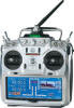
Modern digital transmitters with 100,000x the processing capability weigh less than
a pound. Being a tube circuit admirer, I have always been impressed at what designers
were able to do with so little. Some day our kids will look back at the Futaba 14M
(pic to the right) and wonder how we managed to keep model sin the air with the
need to actually hold a transmitter at all (brain wave control will be standard
equipment). If you like re-visiting the old days of radio
control (notice I didn't use the adjective "good") to see how far we have come in
terms of equipment, then this article from the January/February 1963 edition of
American Modeler magazine is just what you are looking for. Dr. Walter
Good (no relationship to the adjective mentioned above) developed this "handheld"
transmitter at a featherweight seven pounds to replace his previous 32-pound monstrosity.
Modern digital transmitters with 100,000x the processing capability weigh less than
a pound. Being a tube circuit admirer, I have always been impressed at what designers
were able to do with so little. Some day our kids will look back at the Futaba 14M
(pic to the right) and wonder how we managed to keep model sin the air with the
need to actually hold a transmitter at all (brain wave control will be standard
equipment).
WAG - Hand-Held Relayless Dual Transmitter
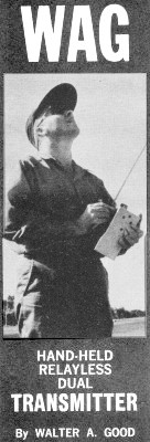 By Walter A. Good By Walter A. GoodIt was probably the jibes
from my "friends" that caused me to develop this handheld transmitter for the WAG
Dual Proportional TTPW control system. In particular, it was becoming very difficult
to sign on a contest mechanic because they all knew about my heavy 32 pound transmitter
with its old fashioned Y antenna! Now with a new hand-held transmitter weighing
only seven pounds, my friends are again more helpful. It was certainly worth the
effort to regain their confidence!
The handheld transmitter is not just a repackage of the old dual system, it has
several new features. Most important is the elimination of the pulser relays. Besides
the problems with dirty relay contracts and bouncing relay contacts, I found it
very difficult to make a relay-pulser which did not have "lag" troubles. This "lag"
problem showed it-self as a shift of the neutral position when you tried to speed
the pulser from four cps to ten cps. Or worse yet, with the stick at one end you
would get 20/80 and the other end, 100/zero! The relay-less pulser cures this problem.
And no contacts to clean and adjust! As a result, "rate-buttons" have been included
in the transmitter to step the pulsing from four cps to ten cps for additional functions.
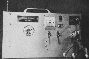
Other features are tiny center-reading meters permanently wired to the two pulsers
so the pulser operation can be easily monitored. Since there are no clicking relays,
monitors like the meters are necessary. No, flying your plane in the fog by watching
the pulser meters is not recommended! Incidentally, the meters come from Lafayette
Radio as FM tuning meters with a rating of 50-0-50 microamperes at a price tag of
$2.95. They are the two small rectangular meters in the photograph.
The transmitter uses surplus nickel-cads and a DC/DC converter for the power
supply. The RF section has a low-power switch which permits short range "distance"
checks.
The handheld was used for the entire 1961 flying season with good results. It
was on 53 mc and steered the Stink Bug with proportional ailerons, elevator and
three speed engine. Rudder control replaced ailerons in medium engine speed and
split drag-flaps were positioned down or up with a long engine pulse. Maynard Hill's
copy on 51 mc has also performed well, especially on his 10 ft, dual proportional
glider. His "fail safe" worked on a motorized tow-release.
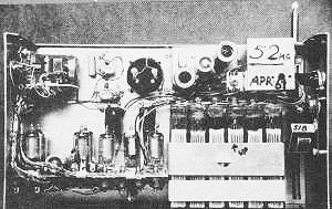
Good's "handheld."
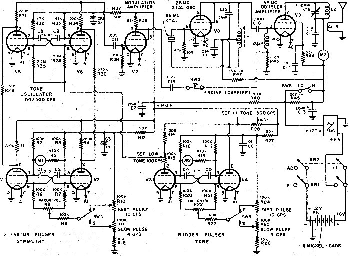
Values for L1, 16T #22E-CTC 3/8"-Red Slug, Tap at 4T;
L2, 8T #16 - 1/2" ID - Air; L3, 2T #16 - 3/4" ID - Close to L2.
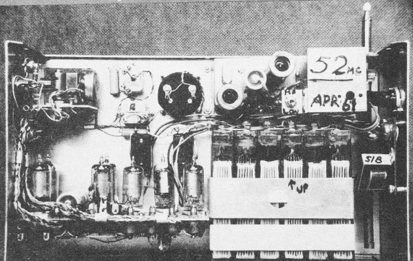
Overall chassis wiring shot.
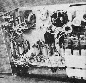
Close-up of left side of chassis assembly & wiring.
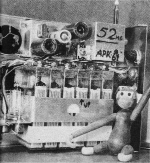
Close-up of right side of chassis assembly.
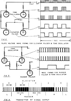
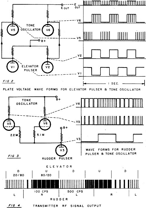
WAG transmitter timing diagram.
Probably the nicest feature was the self-contained aspect of the handheld. No separate
control box to forget, and even the 7-section antenna is permanent. Its 8 1/2" slides
almost completely into the box when stored and then extends to 48 inches in use.
It's European and available from Polks in NYC.
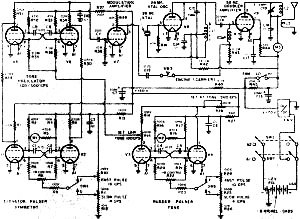
Now let's look at the circuit details of the transmitter. All together there
are nine tubes. Two each in the two pulsers, two in the tone oscillator, one for
the modulation amplifier, one in the RF crystal oscillator and one in the RF doubler
amplifier. The MOPA transmitter is exactly like the old TTPW 50 mc version as described
in the March 1957 AM. The circuit diagram of Figure 1 shows the complete pulser-modulator,
transmitter and power supply.
The purpose of the TTPW (Two-Tone-Pulse-Width) pulser is to generate a 100 cps
tone with either 80/20 or 20/80 tone symmetry or a 500 cps tone with 80/20 or 20/80
tone symmetry. Left rudder is 500 cps, right rudder is 100 cps. Up Elevator is 80/20
tone symmetry and down Elevator is 20/80 tone symmetry. Thus the Rudder pulser pulses
between 100 and 500 cps tones and the Elevator pulser pulses between the 80/20 and
the 20/80 symmetry. The engine escapement is worked by a blip of carrier.
The tone oscillator is a pentode multi-vibrator using two 3V4's, V-5 and V-6.
The feedback is between the screen grids and control grids through the 0.0015 capacitors
C-8 and C-9. The 80/20 symmetry is generated by making the grid resistors unbalanced.
Note that R-35 is 2.2M and R-36 is 5.1M, hence V-5 will put out 20/80 symmetry and
V-6 will put out an 80/20 symmetry. Now all that is necessary to generate the Elevator
signal is to switch the output of the tone oscillator from the plate of V-5 to the
plate of V-6. This is done by the Elevator pulser. Note that the only plate voltage
for V-5 comes from the plate of V-1 and the voltage for the V-6 plate comes from
the plate of V-2. When the Elevator pulser is operating, the plate voltage of V-1
(and hence V-5) will be about 10 V (V-1 conducting) and the plate voltage of V-2
(and hence V-6) will be near 140 V (V-2 non-conducting). The voltages reverse with
every pulse. Thus V-5 first has high voltage and then V-6. The two resistors, R-31
and R-34, mix these two outputs together and C-11 sends them to V-7, the modulator
amplifier, About 30 V peak-to-peak audio appears at the V-7 grid, so it operates
in a saturated mode and puts out a signal with over 100 V swing. See Figure 2 for
the waveforms. Only the 500 cps tone is shown here to clarify the graph.
The tone oscillator will change frequency if the grid return (junction of R-35
and R-36) voltage is changed. This is done, by the Rudder pulser. The pulsing voltage
from the plate of V-3 varies from 10 V to 140 V and is applied to the grid of the
tone oscillator. When the V-3 plate is at 10 V, the tone oscillator gives 100 cps
and when the V-3 plate is 140 V, the tone oscillator gives 500 cps. To obtain an
accurate frequency value, R-15 may be varied to set the 100 cps tone and R-28 to
set the 500 cps tone. Figure 3 shows the tone change that would exist at the plate
of V-5 and V-6 if they were supplied with a steady B voltage instead of the Elevator
pulser voltage. When the symmetry and tone changes of Figures 2 and 3 are combined
and sent to the RF section, the transmitted RF signal is shown in Fig. 4. In this
example the pulsers have different rates so we see all the combinations of tone
symmetry (20/80 and 80/20) and of tone frequency (100 and 500 cps).
Let's take a closer look at the pulser circuits. Since the two pulsers are almost
identical, we will discuss only the Elevator pulser composed of tubes V-1 and V-2.
Here again we have a multivibrator with the feedback between the control grids and
screen grids through the 0.15 capacitors. The one megohm 60° control pot varies
the pulse width from 20/80 to 80/20 and results in the conventional pulse-proportional
response. The meter, M-1 (50-0-50 microamperes), between the screens monitors the
pulser action by accurately following the motion of the control stick. At 50/50,
it stands at the center and wiggles at the pulse frequency. With the stick at either
end, the meter is at the corresponding maximum. The 470 K range resistor, R-5, is
selected to permit full meter movement. The pulse frequency is varied from 4 cps
to 10 cps by the setting of the pots, R-10 and R-11. A switch, SW4, has been provided
to quickly change the pulse rate to operate a pulse rate circuit in the receiver.
The resistor, R-9, helps to keep the pulsing frequency constant independent of the
one meg control pot setting since most multi vibrators of this type tend to speed
up with the stick at either end. The pulsing frequency should vary less than one
cps for all positions of the control stick.
If you wish to stop the pulser in "up" or "down" just apply a negative 45 V to
one of the grids. This tube becomes non-conducting and its mate becomes conducting.
The result is a steady output of the appropriate signal.
The whole set of seven Pulsers-Modulator tubes have a plate current drain of
only 7 ma. at 140 V. Stable operation of the circuit was found to exist over a range
of plate voltage from 120 V to 180 V. Note that all of the 3V4's are run on "half
filaments" so each one has a filament drain of 50 ma., or a 7-tube total of 350
ma. The +140 V supply is obtained' by dropping down from 170 V and is filtered by
R-40 and C-7 (20 MFD) to prevent noise from the power supply from interrupting the
pulsers.
The modulation amplifier presents about 100 volts of audio through C-12 (0.2
MFD) to the grid of the 3B4 doubler. This is more than required to completely cut
off the 3B4 and gives close to 100% modulation. The switch, SW3, is opened to remove
the audio and permit the RF section of the transmitter to emit only ,a carrier wave.
The RF section draws a peak plate current of 29 ma. during carrier only so the peak
current from the DC/DC converter is 36 ma. at 170 V. While pulsing, the RF current
drops and the total average plate current is 27 ma. SW6 introduces a 20 K resistor,
R-45, and drops the RF plate supply to about 40 V. This gives a low power signal
and is excellent for transmitter adjustment and receiver tuning at close range.
The RF filament drain is 430 ma. which, added to the pulsers, gives a total filament
load of 780 ma.
Toggle switch, SW1, turns on the Pulser-Modulator and SW2 turns on the RF section,
In this. way you can turn on the pulsers and show your friends the dancing meters
without emitting any RF signal.
The layout of the handheld was determined by the position of the control stick
in the upper right hand corner of the box. This was found to be an easy spot to
hold the stick with the right hand while the box is cradled on the left forearm.
The fingers of the left hand reach to buttons on the right hand end of the box.
The batteries were placed on the left end of the box so the weight would rest high
on the forearm. The six nickel-cads weigh about 3 1/2 pounds so they constitute
half the total weight.
As seen from the photos, the Pulser-Mod deck carries seven tubes mounted below
the stick and the two-tube RF section is tucked into the space above the batteries.
The writer is indebted to West Coast DC/RC member Bill Saks for the detailed layout
and wiring of the Pulser deck and RF deck. His neatness may be hard to duplicate
but it is probably responsible for the high reliability enjoyed with the transmitter.
The box is a standard aluminum one, 12" x: 7" x 4", which has been thinned down
to 12" x 7" x 3 1/4" by cutting 3/4" from the mating halves. It was thought that
4" of depth would have felt too awkward for easy control.
The finish on the box was simple and very attractive. After cutting and drilling
all of the holes, the outside of the box is "buffed" on a belt sander giving it
a scratched finish. Then a 10 minute anodize hardens the surface and gives it a
satin luster. The hot sun reflects nicely from this surface so the transmitter stays
quite cool. One point of caution: the aluminum can easily be eaten away by the potassium
hydroxide from the nickel-cads. A coat of clear dope around the battery area seems
to help. The cells I used had rubber sleeves at the top. The sleeves were pierced
with a needle so that the pressure during charging would not build up so high and
splatter electrolyte around.
Access holes are made in the back cover for the RF-Hi-Lo switch and to observe
fluid level in the cells. Another hole is placed ·above the RF capacitor, C-19,
so the final amplifier may be peaked with the case in place. This hole is protected
with a rubber, grommet since there's a 170 V on the capacitor shaft and you may
want to tune with a metal screwdriver !
The control stick uses two 60° one meg pots and they are mounted similar to those
in the ACE kit. The "scissors-type" centering spring has been added to each pot
shaft to give a snappy center return. It has been found that better proportional
flying is possible if the rudder pot can be moved individually without moving the
elevator pot and vice versa. Hence the desire for separate centering. The photo
shows the compactness of the control stick and pot assembly.
The antenna is mounted on a piece of 1/16" epoxy-glass board in the corner of
the box so that it remains in the main box when the rear cover is removed. The corner
of the cover is trimmed off to miss the antenna support.
The DC/DC converter (6 V to 170 V) is mounted between the batteries and the end
of the box. One of the Diem units (Model # 518 gives 170 V at 29 ma.) has been used
in this spot. The converter uses five nickel-cads (6 V) and the remaining cell powers
the filaments. The filament cell positive is grounded and the negative is led to
the filament switch. This reversal from normal practice permits the six cells to
be charged in series. The seven-pin socket just above the converter is not shown
in the circuit diagram but it connects to all six cells. A separate meter plugs
into it to monitor each cell voltage after the flying session. The same meter monitors
the cell voltage during the charging period.
Notice the carrying handle which was lifted from an old Heathkit and is mounted
quite a bit off center. Actually, it is right over the c.g. of the box and hence
the carrying level is horizontal.
The experience with the handheld transmitter has been very good. No crashes have
been attributed to a malfunction of it! We have other good alibis for our crashes!
On one occasion, I tried to fly, unknowingly, on low power RF and didn't realize
it until the plane started kicking "up" and "right" about 600 feet away. Quickly
flipped to high power and the plane straightened out. Another time, one nickel-cad
in the transmitter went dead but the plane kept on working.
There have been occasional kicks of the plane controls indicating the passing
through of a signal null. Almost every time this happened one of the following conditions
has been present:
1. Receiver was off tune and needed re-tuning.
2. I was standing in line with several tall ground-based antennas which were
blocking the signal in one direction.
3. Flying from reinforced concrete runways which seem to give a sharp reflection
and a consequent momentary null.
None of these kicks was catastrophic but they don't look good in the middle of
a procedure turn!
Although in the past I've always worked to keep the Rudder and Elevator pulse
frequencies well separated, I was surprised to find the best operation for this
transmitter was when they were made the same. Thus, I find that both Rudder and
Elevator are being pulsed at 4 cps. This holds well for the all stick positions
out to half deflection. From there out the frequencies are slightly different but
no serious "beating" or interaction takes place. On the ground the interaction between
the controls is noticeable at 10 cps but in the air it is not possible to see the
plane react when switching either Rudder or Elevator from 4 cps to 10 cps or back.
The next project is to put some rate detectors in the plane to use these rate changes.
The Dual system would then give two proportional controls, engine escapement and
two on-off controls.
In tuning the pulsers the meters give the best indication. Just center the control
stick pot to center the meter. The stick should have enough freedom of motion for
the meter to indicate its maximum reading just before the stick hits the edge of
its hole. The wiggle of the meter may be damped by placing a 100 MFD, 6 V electrolytic
across it. This has been tried and worked for several months, but since the voltage
on the meter has both polarities, one of the capacitors went bad and shorted out
the meter. These capacitors have now been removed.
The tones may be set by removing tube V-1 to stop the symmetry pulsing and then
removing tube V -4 which leaves only the low tone. Now adjust pot R-15 to give 100
cps using an audio oscillator as a reference. To set the 500 cps tone, replace V-4,
remove V-3 and adjust R-28. These controls interact slightly so it may be necessary
to do this several times to obtain an accurate setting. Once set, the tones should
hold very well.
The RF section is checked out first on low power with the pulsers off. Tune L-1
until a monitor receiver indicates that the crystal is oscillating; also a downward
jump in M-3 will take place. It has been found that the 50 mc transmitter requires
a very active crystal. Both ACE and International crystal units have worked well.
Then tune C-19 until a nearby field strength meter (FSM) gives a maximum reading.
Re-tune L-1 until it is about 1/4 turn from where the oscillations cease. Now try
L-3 antenna coil closer to L-2 and re-tune C-19. Try different spacings until you
obtain the best FSM reading with the. smallest RF amplifier plate current on M-3.
All of the foregoing may be done with the back cover removed. Before attaching the
cover, switch to high power and place the FSM some distance away; 12 ft. is just
right for mine. And check tuning of L-1 and C-19 for the best output but leaving
L-1 on the safe side. Put the cover in place and make one final touch up of C-19.
Flip on the pulsing and the FSM should drop to about half. Moving the Elevator stick
should cause a variation in FS while the Rudder should not. Now she's ready to go
to the field!
There are always some improvements that could be made in a new device. I expect
the six 9 1/2 oz. (3/4" x 2 5/8" x 4 1/2") plastic nickel-cads I used could be replaced
with a smaller sealed type. The 9 1/2 oz. type were rated at 5AH and give almost
four hours of safe flying on a full charge since the current from the 6 V supply
is 1.1 amp. Probably a size-D sealed cell of the 4AH sintered type would give well
over three hours. They would also take less space and lighten the transmitter considerably.
Some of the 6 oz plastic types would also be suitable.
A little more RF power than the present 1/2 watt would be desirable. One way
to get more radiation would be to use a "loaded" antenna with a loading coil in
the center. I gave this a quick try using the Graupner antenna, but came up with
no improvement on the FS meter. Just why I don't know, but it should help. Another
help would be a "straight-through" amplifier of 50% efficiency instead of the doubler
with its 25% efficiency. Look at the MAC 50 for ideas on this (ATMA, 1961).
The possibility of a trim control on both the Rudder and Elevator would be handy.
Right now this must be done by mechanically shifting the pot relative to the stick,
and of course, only between flights. In-flight trim would be more desirable, especially
with a new plane.
The handheld has not been tried on 27 mc as yet. There is reason why it won't
work just as well there.
Although this has not been a constructional article, it is hoped that some of
the ideas and circuits will be useful to the large family of proportional experimenters.
The list of parts required for the trans-mitter follows:
PARTS LIST
Meters
M-1, M-2-FM tuning meter 50-0-50 microamp. Lafayette TM-13 M-3-0-50 milliamp.
Lafayette TM-402
Capacitors
C-1, C-2, C-4, C-5-0.15 MFD, 100 V. Mylar, CD type WMF1P15, tolerance ± 10% matched
in paris
C-3, C-6, C-17, C-18-0.01 MFD Disc Ceramic, Erie type ED-.01
C-7, C-13-20 MFD, 250 V, Electrolytic Sprague TVA-1508
C-8, C-9-0015 MFD, Mica, CD type CD19F5D15, tolerance ±5%
C-10-0.1 MFD, 100 V, Mylar, CD type WMF1P1E
C-11-.0051 MFD, Mica, CD type CD30F5D51
C-12-0.22 MFD, 200 V, Mylar, CD type WMF2P22E
C-15-5 MMF, Mica
C-16-10 MMF, Mica
C-19-3-12 MMF, Variable Air
Resistors
R-1, R-4, R-18, R-31, R-34-220 K, 1/2 watt, 10%
R-2, R-3, R-6, R-7, R-9, R-16, R-17, R-20, R-21, R-23-100 K, 1/2 watt, 10%
R-5, R-19-470 K, 1/2 watt, 10%
R-8, R-22-ACE #JU60°, 1 megohm, 2 watt
R-10, R-11, R-15, R-24, R-25, R-28-100 K pot, small size, 1/2 watt
R-12, R-26-10 K, 1/2 watt, 10%
R-13, R-27, R-37-150 K, 1/2 watt, 10%
R-14-120 K, 1/2 watt, 10%
R-29, R-30-270 K, 1/2 watt, 10%
R-32, R-33, R-41-47 K, 1/2 watt, 10%
R-35-2.2M, 1/2 watt, 5%
R-36-5.1M, 1/2 watt, 5%
R-38-10M, 1/2 watt, 10%
R-39-82 K, 1/2 watt, 10%
R-40-5-1 K, 1/2 watt 10%
R-42-15 K, 1 watt, 10%
R-43-2.2M, 1/2 watt, 10%
R-44-33 K, 1/2 watt, 10%
R-45-20 K, 1 watt, 10 1/2
Switches
SW1, SW2-Toggle DPST
SW3-Push button, SPST, NC
SW4, SW5-Push button, SPDT
SW6-Small Toggle SPST
Tubes
V-1, V-2, V-3, V-4, V-5, V-6, V-8, 3V4
V-7, 1L4
V-9, 3B4
Antenna
Aristo-Craft 6-E (available from Polk's, NYC)
Posted August 14, 2022
(updated from original post on 9/9/2012)
|