When I wax nostalgic about old
tube radio sets, it is not because I don't appreciate the performance and quality
of modern electronics. It is just that a lot of the technology was still mainstream
when I was young (born in 1958). I remember having it in my parents' house and seeing
even older stuff in my grandparents' house. Some people's midlife crisis takes the
form of wearing age-inappropriate clothing, gold jewelry, and chasing after strange
women. The manifestation of my "crisis," if you want to call it that, has been collecting
memorabilia from days of yore. There is a huge demand for it, so I make as much
as I have time for posting available for others to enjoy. Articles like this one
are from old editions I bought on eBay, a 1963 edition of American Modeler
magazine in this
instance. Even though nobody will go out and buy parts to build this tube-based
R/C transmitter, there are useful descriptions of circuit design considerations,
including the use of a center-loaded, half-wave antenna. Hams eat this stuff up.
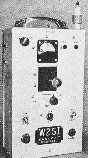
Enjoy."Handy-Mac" 50-mc R/C Transmitter

Engraved name plate adds class!
Our radio control advisor finally ROG's (rises-off-the-ground) with a potent, hand-held
transmitter guaranteed to make any properly tuned receiver behave 100% good like
a receiving set should!
By Howard G. McEntee
Efficient antenna and output stage assures good power from this hand-held 50-mc
R/C transmitter, yet you get reasonable operating time from each battery charge.
It's suitable for Kickin' Duck, Galloping Ghost and other pulse rate and length
control systems. A deluxe outfit, yes - but advanced modelers can pick out the features
best suited for their own use. The RF section is fine for tone or CW receivers,
the modulator is stable enough for reed or filter use, the pulser is adjustable
for practically any need.
Having long felt the need to be freed from the physical restrictions of a ground
type transmitter, Handy-Mac was in the planning stage for several years. Our philosophy
calls for a rather potent transmitter (which includes an efficient antenna system)
and fairly insensitive receiver (mainly to reduce troubles from interference due
both to other transmitters, and to "electrical noise" generated in the plane) so
prime design goal here was lots of signal out in the air. A "straight-through" final
amplifier with a tube designed for RF use at these frequencies, and a center-loaded
antenna were considered basic. Also, a power supply capable of relatively high voltage
was a necessity.
Antenna slides into insulated tube.
Black blob is taped pack of nickel-cads.
Planned at the start was a nickel-cad battery, and a transistor converter. Then
there were plenty of ABC #2 nickel-cad cells available, and the case was chosen
to allow six of these to fit snugly across the back. These cells are now rare, but
six of the ABC #1 cells can be squeezed in; or, six of the much higher but thinner
surplus cells of the type sold by Esse Radio can also be adapted. All these cells
seem to be rated around 5AH capacity, and all would give fine results. However,
about a year ago the 4AH sintered plate nickel-cad sealed cells were announced by
Gould, and the advantages of the sealed cells were worth making design changes to
accommodate. These cells are very clean, never have to be filled, are much smaller
and lighter than the surplus plastic-case cells (they are the same size as D flashlight
cells). They will stand the current drain of the transmitter with no trouble at
all, and have proven ideal for this application. With the surplus cells we had intended
to mount the battery and the converter on the rear of the case; use of the Gould
4.OSC cells allowed everything to be mounted in the main portion of the case.
The case itself is "special," in that it is the only one we know of which is
made in the manner you can see in the photos (front, two sides and one end are all
in the main unit). It is of .050 aluminum, and thus rugged enough to withstand the
beating field equipment like this takes. The case can be had in plain aluminum or
gray paint; we chose the former, since it reflects heat much better (glow fuel soon
makes painted cases look crummy). The case was gone over with very fine emery paper
to give it a "grain," then was given an alkaline etching followed by clear anodizing.
The latter two processes were done commercially, cost $4. Anodizing is a very hard
tough finish, helps prevent all the little scratches that soon mar soft aluminum
surfaces.
It was decided at the outset that since we would probably be using this transmitter
for quite a number of years (the old Mac-50, which was forced into semi-retirement
by the Handy-Mac, was in constant use for about 10 years) the various components
would be made up in sections which could be removed fairly easily, and replaced,
when new ideas came along. Thus, the RF section has its own chassis, and there is
another for the modulator and pulser. Power supply components are easily removed.
Since we were after lots of RF efficiency, one of the most efficient tubes we
know for the output amplifier is the 3B4. It has another asset we make use of-a
designed filament voltage of around 1.25 volts. It's undoubtedly true that a single
nickel-cad cell on the filaments of tubes intended for use with regular dry cells
(such tubes have a "design center" voltage rating of 1.4, will give good results
over a range of perhaps 1.3 to 1.5 volts) results in at least shorter life and definitely
lower output. This is especially so when the tube is being run up near its maximum
current ratings. Our 3B4 is really just loafing, and is getting a voltage it's designed
for, even when the filament cell sags down a bit as the charge is dissipated. All
the other tubes in the transmitter are operated at much below maximum current ratings
- which is how we justify operating them on a single nickel-cad cell too.
Some tries were made at using 50-mc crystals, with just an oscillator at this
frequency feeding the 3B4 amplifier. While good output could be had, everything
had to be run right on the upper edge, and it just didn't look too practical. So
we fell back on the old faithful 3A5 as 26-mc oscillator and doubler, to feed the
3B4. Thus the circuit is very much like the Mac-50, but we did use a simpler and
neater neutralizing circuit, and slug-tuning for the doubler.
Since a transmitter of this complexity won't be tackled by beginners, we are
skipping exact cutting details for the case, chassis and other parts. The photos
show where parts are mounted, and the more experienced builder will doubtless want
to use parts he has on hand, which might require some shifting back and forth.
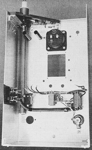
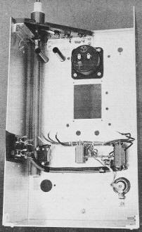
The transmitter chassis is L-shaped, attaches to the front and the side of the
case. In the underside view, note all parts which project under the chassis are
mounted along one edge. This allows clearance for the antenna, which collapses almost
completely into the case. Only item along that side of the chassis is a lug strip,
which carries most of the resistors. No commercial strip could be found to fit out
specs, so one was made, using a 3/8" wide strip of 1/16" thick fiberglass epoxy
sheet; lugs are rivet type (Ace #ELI are suitable).
L4 and L5 are supported by their tuning capacitors, which have slotted shafts;
tuning is through holes in front panel; to guide screw driver to slots, lengths
of phenolic tubing are fitted in holes and run back over the stub capacitor shafts.
Tubing also prevents shorts and "fireworks" if non-insulated screwdriver is used.
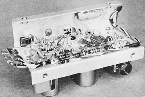
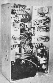
Underside of RF chassis.
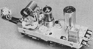
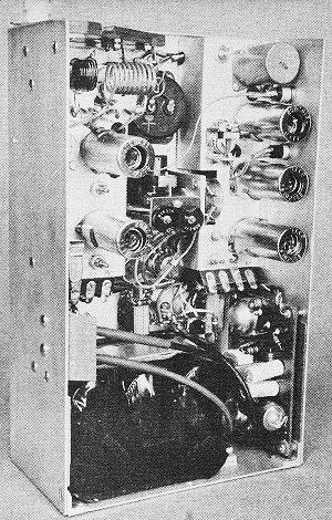
RF chassis top, note clamp holding crystal.
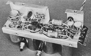
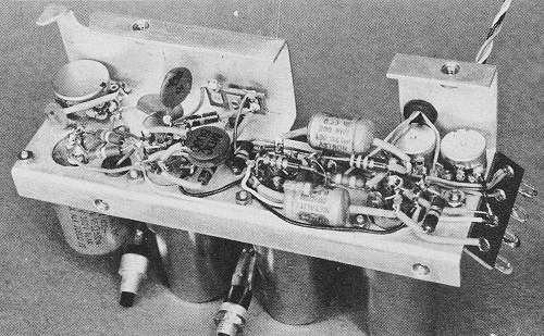
Bottom of pulser/modulator
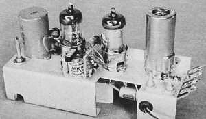
Pulser/mod topside, all tubes use shields.
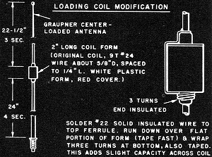
Loading coil modification.
All tubes in the transmitter are mounted in sockets which have detachable shields.
The crystal socket is fitted with a spring clip, which holds the crystal firmly
but allows easy removal.
It will be seen on the RF unit circuit that a switch is used to shift the single
meter to various places, for monitoring current - and voltage. SW4 does this, is
considerably larger than we had figured on, and had to be squeezed in. In case some
readers spot the Lafayette SW-78 as an ideal choice for this spot, (as we did) don't
use it; it is a shorting type, not suited for this purpose. The larger Mallory unit
can be fitted in with care.
A lug strip was mounted at lower edge of each chassis, to make for easier attachment
and removal of power leads. Since most of the leads to SW4 come from the RF chassis,
this switch is wired to the chassis and has to be removed with it.
How about that collapsible antenna? It is a center-loaded type, can be used just
as it comes (though we made a slight modification, see sketch) and gives us the
advantages of a full half wave radiator - not the more usual quarter wave. One of
these advantages is that the case of the transmitter is "stone cold" RF-wise. With
the usual quarter wave antenna, the case, the operator and even the ground he stands
on are all part of the overall antenna system. If all are matched up right and the
transmitter is tuned to match also, the antenna will put out well. But difference
between such factors as dry or wet hands (moist or dry atmosphere) can make quite
a difference in output.
(Right here someone is bound to bring up the point that many thousands of commercial
HH transmitters with such antennas have - and do - work fine. Agreed, but the aim
was to make the Handy-Mac antenna system even better).
A true half wave antenna is complete unto itself - it doesn't depend upon the
operator's shaking arms for part of its "circuit." Anyhow, by proper selection of
parts and correct tuning, we have been able to reduce the RF on the case to practically
zero; the transmitter will show almost exactly the same FSM reading when hand held,
placed on the ground or up on a wooden table. Also, the amplifier plate current
doesn't change appreciably under these different conditions. No really exact comparisons
have been made, but FSM and other checks with transmitters having about the same
input to the final amplifier show much greater output for the Handy-Mac. Part of
this may come from the highly efficient RF amplifier - but part undoubtedly also
comes from the antenna.
We were able to locate a commercial antenna that is almost exactly what is required
- a German unit made by Graupner, and intended for use on the overseas 40-mc R/C
spot. Due to the loading coil, this antenna is considered quite a "custom" unit,
and costs considerably more than the plain types, around $6. We feel it is well
worth the cost, especially in view of the fact it collapses almost entirely into
the transmitter. Only 2 1/4" projects above the top. You can never forget your antenna
with this type, and you don't have the nuisance of detaching it, when the transmitter
is not in use. For those who get this particular unit, note that the section just
above the loading coil pulls out very easily, up to the last 1 1/2"; be sure you
get it all the way out, or the loading coil will be shorted.
Just to make sure the bare antenna doesn't short anything when it is collapsed,
we fitted a phenolic tube (this comes from another antenna sold by Polks) for it
to slide into. The modification mentioned earlier is shown on the drawing, which
also gives rough measurements for those 50-mc R/Cers who want to try making their
own center-loaded job from other parts. We found the final antenna, suspended from
the ceiling and with 2" lead soldered to lug on mounting (this lead attaches to
C5, when antenna is on case) resonated at about 49 mc with a grid dip meter.
An output monitoring circuit is built into the transmitter, the antenna of which
is the handle atop the case. This handle is a type sold for kitchen cabinets, comes
with a couple of decorative plastic "insulators." A spring is mounted to contact
one of the handle screws when the cover is in place; then with the meter switch
on terminals F-G, actual RF output can be monitored. The reading drops way down
when the handle is not in the circuit.
A few notes on the meter switching circuits. Switched to A-D, oscillator plate
current may be measured, R1 being chosen to shunt the normal 1-ma meter up to 10-ma.
Shunts will have to be selected to match the meter you employ; for the specified
meter, about 9.1-ohms did the job. Next meter switch position puts it across R2;
this gives grid current of the 3B4, with the 1-ma meter reading a few percent low,
due to shunting effect of R2; R3 is selected to shunt the meter to 30-ma, for amplifier
plate current. Switch SW4 terminals H-C connect the meter across five cells of the
power supply - those that drive the DC converter. Since drain on these cells is
a little heavier than that on the filament cell, it was felt the latter did not
need metering.
With only a single cell for filaments, every effort must be made to keep voltage
drops in the filament circuit as low as possible. This means all filament leads
should be of heavy wire (#12 stranded was used here). To raise total drain on the
filament cell to near that of the cells driving the converter, a rather heavy drain
pilot lamp is employed. We found a G.E. #123 about right; it is rated at 1 1/4 volts
and 0.3=A.
Having seen the destruction that can be caused in a transmitter when there is
a short on the nickel-cad power supply, fuses were fitted in both battery circuits.
The Gould cells have solder lugs for intercell connections, are taped up into
a solid package and held in the case with an aluminum strap. We took a tap off every
cell, and these all run to the 7-pin socket on front of the case. The end terminals
are used for charging. A voltmeter can be connected across each individual cell,
for monitoring voltage.
We found the Diem converter could be attached to the case side below the audio
and pulser chassis. This converter was chosen because it has two separate output
voltages, high for the RF circuits and modulator, and another output of 45-volts
for the pulser. The converter is a type originally intended for TTPW transmitters
and ideal for this outfit.
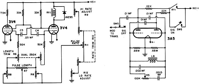
"Handy-Mac" Pulser
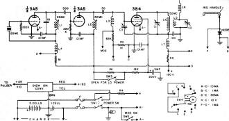
RF and Power Sections

Modulator Circuit

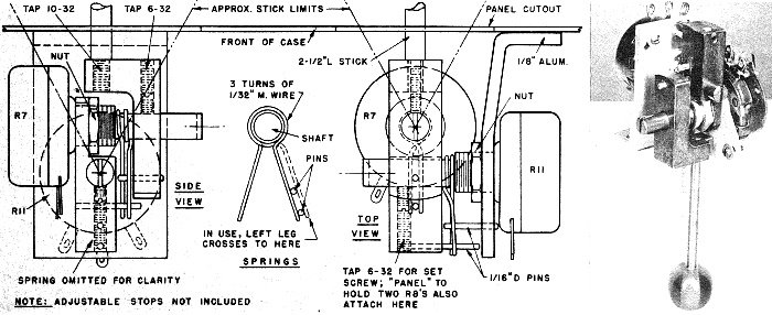
Control Stick Mechanism Is Shown Actual Size
Parts List:
Listed are the most specialized units in transmitter; many which are standard
are not included. All resistors are 1/2W carbon.
R1, 100 and 10-ohm carbon in parallel;
R3, 3.3 and 33-ohms in parallel;
R4, 10K (these three must match particular meter used);
R5, 100K, Mallory
1/2" dia. (Lafayette VC 536);
R6, dual linear 250K (see text);
R7, special
1-meg linear (Ace 60 degree type);
R8, both 5-meg (CRL type B16-128, knobs removed);
R9, 200K, Mallory 1/2" dia. (Laf. VC 537);
R10, dual 10K (see text);
R11, special 100K linear (Ace 60 deg. type);
R12, 50K Mallory 1/2" dia. (Laf.
VC 535).
C1, C2, 15-mmf APC type (Laf. HP-10);
C3, 1-7-mmf CRL ceramic trimmer
(Laf. CA-375);
C4, C5, .25-mf tubular paper sub-min (Ace "Aerolite"); all capacitors
in modulator, all those in RF section except .01-mf should be low temp. coefficient
ceramic.
SW1, SW2, SW3, toggle sw., lugs on ends;
SW4, Mallory 2 pole, 5
pos. non-shorting rotary (Laf. SW-367);
SW5, NC push button (Grayhill 30-2);
SW6, NO push button (Grayhill 30-1).
F, dual fuse holder, 3-A fuses (Laf.
E1 373 and E2 230 fuses).
All sockets and shields, Elco (Laf. MS 495 and MS
499).
Case, LMB type EL 1063, 10 x 6 x 3 1/2" (Newark Electronics, Chicago).
Crystal, Ace 26 mc, Int. Crystal 25.5 and 26.5 mc units have been used here.
L1, type LS6 1/4" dia. ceramic coil form, 10T, #26E wire, red dot core;
L2, same form, white core, 10T #26E (Ace forms used);
L3, 22-uh RFC (Gyro);
L4, 9T #14, 1/2" ID, 1" long;
L5, 7 1/2T #18E, 1/2" ID, close-wound, 3/8"
from L4;
L6, part of Graupner antenna (Polk's);
L7, 70-uh RFC (Gyro);
L8, Gyro T9643 AF choke.
All tubes, Gyro. Meter, sealed 1-ma, 1 3/4" sq.
(Gyro model HS 1).
When laid out at the beginning, there was no intention of fitting pulse rate
and length trim controls, and no room was left for them. Thus, a final decision
to include these controls found us with no room for standard size dual pots, and
holes had already been drilled in the front of the case for all switches etc. On
hand were a couple of special Centralab dual pots of 5/8" diameter, and these were
pressed into service. If trim pots are planned on from the beginning, the more standard
size duals could easily be fitted on the case front. To assure maximum space behind
them for the converter and battery, panel switches should have shortest possible
"neck" and be of type with lugs projecting from ends, rather than rearward.
The pulser is a rather conventional multi-vibrator, very much like the original
WAG type using a pair of 3V4's. A number of variable adjustments were included,
to make it possible to "tune" the pulser to an existing plane fitted with Kickin'
Duck, or for any other control system likely to be tried. Thus, in addition to pulse
length trim (R6) and Rate trim (R10) there are pots for high pulse rate setting
(R9), low pulse setting (R12) and two more (R8 and R9) that have been found useful
in the Kickin' Duck system (see article in A.M., Sept. '61).
The main pulse length and rate pots, R7 and R11 are of special type giving full
resistance change in only about 60 degrees of. shaft rotation. The compact control
stick assembly is shown in some detail, utilizes "clothespin" type springs for positive
centering. Adjustable stops are built in, but some builders prefer just to let the
edge of the case opening, through which the shaft protrudes act as a "stop." Resistors
R8 ride on the back end of control stick assembly held by a small phenolic plate.
Main problem with control stick mounting of this sort is to arrange the leads from
R7 so they are free to move as the stick is varied, but so they won't rub on other
parts or break at the ends.
Since space is at a premium, a slot had to be cut in the modulator chassis to
accommodate R11. On this chassis, the two 3V4 tubes are at bottom, 3A5 modulator
above them, and stabilizing inductor L8 at top. The pulser relay is what is generally
known as the "Bramco" type, has armature contact insulated from relay frame. This
may have to be procured direct from Jaidinger Mfg, Co.; we obtained palladium bar
contacts, as silver pulser relay contacts in this circuit have not been found to
stand up too well.
Since the writer is left-handed, the transmitter is cradled in the right arm,
with fingers wrapped around the left side of the case (viewed from front) and the
On and Off buttons are on that side. R5, which varies the modulator tone somewhat,
may be seen alongside L8.
To match a receiver now in use, the modulator components were chosen to produce
a tone variable from about 2,000 to 2,600 cycles. 100% modulation is provided. For
info on this type of modulation, see article in A.M. (Oct. '59
p. 25).
We won't go here into the matter of balancing parts for the pulser, as this has
been well covered in past issues of this magazine. For more info, look up references
listed in articles on Kickin' Duck (A.M., Sept. '61; '58 Air Trails Annual).
To keep dirt out of the interior, a leather "boot" cut from a discarded suede
glove is attached to the control stick, with edges held by an aluminum "frame."
Markings on the front panel are cut from special R/C decal sheet supplied by
Ace, and each cutout is given several coats of Lee's Shield, as protection from
the inevitable glow fuel smeared fingers that will be handling the outfit. The sharp
looking name plate at bottom of the case front is an etched job provided by a friend.
Now, about tune-up, operating values. As far as the former goes, we feel the
experienced ham will know how to go about it. The oscillator circuit has just a
slight amount of regeneration, and fairly peppy crystals should be used. Those specified
in the Parts List have been found suitable; other good makes may do as well. After
getting the oscillator and doubler tuned up, and a good grid current reading on
the 3B4, this tube should be carefully neutralized, The set will work with no neutralization
- but it's much more stable and easy to tune with it. Furthermore, we are strongly
of the opinion that many cases of "insufficient modulation," "modulation percentage
too low," and even of "receivers that overload badly close to the transmitter" are
due entirely to leakage of RF power through a final amplifier tube that is not neutralized
(and from these angles it is just as important to neutralize a doubler used to feed
the antenna, as it is a "straight through" power amplifier - anyhow, do a careful
job here).
The coupling coil L5 must be placed to load the 3B4 as desired; C2 is used to
adjust tuning, after L5 has been set roughly, and if latter is right, you will be
able to get proper loading at two settings of C2. In other words, L4 and L5 are
a little over-coupled, then the antenna circuit is detuned slightly to adjust coupling
so the 3B4 plate current is just what you want.
With properly adjusted antenna coupling, fully charged set of nickel-cad cells,
current and voltage values in the outfit are about like this (modulator and pulser
off): high voltage, 166; pulser voltage, 44; oscillator plate current, 6.5-ma; doubler
current, 7-ma; 3B4 grid current, 0.75-ma; 3B4 screen grid current, 4-ma, 3B4 plate
current, 15-ma (antenna coupling adjusted to obtain this value). This indicates
a plate input to the 3B4 of about 2.48W, and power output was measured at 1.4W,
showing a plate efficiency of some 56 1/2% - considered very high for an RF unit
of this sort. The 3B4 plate current drops somewhat with modulation, as is usual
with the, sort of grid modulation used here, so that even though the modulator takes
about 4 ma total, when the tone is on, the drop in 3B4 plate current is about the
same, and overall current drain stays about the same as without modulation, The
pulser also draws about 4-ma (at its 44-volt level) and there is about 2.4-ma through
the 7,500-ohm relay. The relay is set to operate at 2-ma and release at 1.3-ma.
With fully charged batteries, drain on the converter supply is some 1.2A, and about
1.05A on the filament cell. When SW3 is opened, 3B4 plate current is only about
3-ma; this is still a potent signal close by, but for shop use we collapse the antenna
fully (while this detunes both antenna and 3B4 plate circuit, current in latter
stays roughly the same as with antenna extended). This holds true even with full
power, so the transmitter can be used for shop or close range testing with antenna
collapsed, with no tube damage.
Flight tests have shown the transmitter really puts out. As expected, the signal
is not as strong at a distance, and especially with plane on the ground, as with
the old Mac-50. But that is a pretty potent powerhouse; while the 3B4 in the Mac-50
runs at almost the same input as it does in the Handy-Mac, the full length half
wave antenna on the former is undeniably much more efficient, Even to one accustomed
to a very peppy ground based transmitter, we feel the new HH job will prove highly
satisfactory.
Posted March 25, 2024
(updated from original post
on 12/15/2012)
|