|
Imagine if your path to flying
an R/C helicopter involved first designing, then building, and then troubleshooting
the contraption. That was the burden of pioneers. We have people like S.S.P. Helicopter
designer Gene Rock to thank for being able to enjoy the state-of-the-art models
that are available today. This article from the August 1972 edition of American
Aircraft Modeler magazine describes the process of machining all the metal
parts for an Enya .45-powered craft. Mr. Rock even designed a very successful mechanical
gyro for keeping the tail under control. If you have ever tried flying an R/C heli
without any type of gyro (I have, on a DuBro Tristar), you will fully appreciate what a pleasure it is
to not have to manually counter torque changes (throttle) with tail rotor stick
input from the transmitter. Around 2008 I bought a
Blade MCX2 coaxial rotor helicopter for flying inside, and the
gyro is so good on that thing that you can put it in a full speed pirouette in either
direct, release the rudder stick, and the model instantly stops spinning and holds
its new heading - amazing. OK, time to go blow the dust off your model lathe and buy some metal stock. Let's
see if you're up to it. See also Learning
to Fly the S.S.P., and SSP-5.
S.S.P. Helicopter
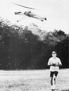
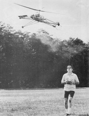
Gene Rock flies his S.S.P. Helicopter
by Gene Rock
I made my first helicopter, inspired by Glen Lee, back in 1962. The model was
free flight and it didn't fly simply because I didn't know how to adjust tip weights.
In 1963, Ken Norris' helicopter spurred me on and the model failed - simply because
I couldn't keep the motors running. In 1967, John Burkam's model in the Challenge
of RC Scale took shape in my shop but still couldn't get off the ground. This time
the problem was mainly due to poor machining practices. In 1969, I met John Burkam
and started building rubber-powered models like "Perini" published in 1969 in American
Modeler. Rubber-powered models offered a fast way to study helicopter stability.
I learned twice as much in the following year as I did in the previous seven. Many
evenings were spent observing John's "Super Susie" in flight. Again I tried and
failed but finally this past summer the "S5.P." emerged. Being so fed up with failures,
the tethering was skipped. A few short bursts of the engine was enough to trim out
the model. Feeling brave, I gunned the engine and the model leaped into the air
and was ten feet off the ground before the engine was throttled back - it has been
flying ever since.
The "S.S.P." is similar to Dieter Schluter's helicopter in every aspect except
for size and body. The rotor system is Hiller except that there is no feedback from
flapping. Rotor control is achieved by applying cyclic pitch to the small paddles.
This forces the gyro that the paddles are attached to, to precess 90° later in the
direction of the force. When the plane of the gyro is changed with respect to the
main rotor, cyclic pitch is applied to the main rotor. Like the gyro, the main rotor
takes 900 to precess. Now the rotor plane is changed, changing the thrust vector.
Assume that we want the model to fly forward: The swash plate is tilted so that
it is high in back. This tilt gives the pad-dies the most pitch on the left side.
This in turn precesses the gyro and makes it high in back of the model. With the
gyro high in back, the rotor blades have the most pitch on the left side. This precesses
the rotor and makes it high in back. The model then flies forward.
Throttle linkage is spring-loaded to eliminate any slop. Precise
control is essential since no collective pitch control is used. Throttle does it.
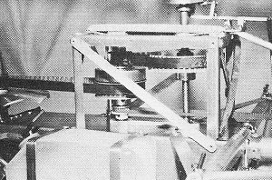
Two stage belt reduction to rotor shaft permits locating centrifugal
clutch on midshaft and the drive to the tail rotor via another belt.
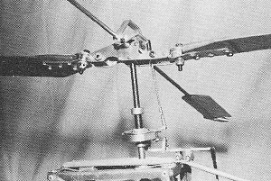
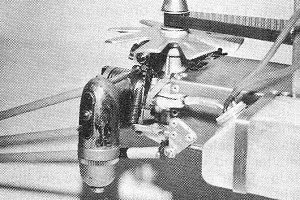
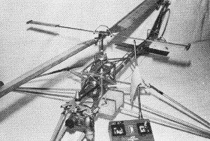
This is a Hiller rotor system except there is no flapping feedback.
Control is through application of cyclic inputs to the small paddles/gyro.
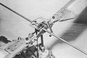
Complete head assembly is free to tilt in any axis. The body
or chassis tends to just hang under the rotor. The gyros keep it stable at all times.
Unique among model helicopters is the gyro on the tail rotor.
This automatically cancels torque variations and wind gust inputs allow-ing the
pilot to concentrate on other flying duties.
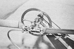
Servo input to the tail rotor is via springs which precess the
tail gyro. Belt drive here is simple and positive. Note rugged components.
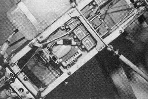
Radio installation worked out to balance the model just in front
of the main rotor shaft. Many Missing Links and Kwik Links are used.
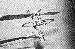
Spindly landing gear system really helps when learning to fly
a chopper. It can be taxied on the gear, too. Note visible and large fuel supply-an
absolute must. Dead stick landings are crashes.
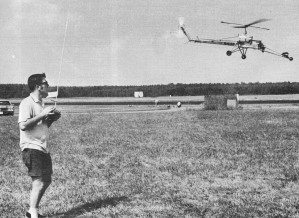
Scene at Dahlgren, Virginia for DCRC Record Trials where Gene
flew the "chopper" to a 650-ft. altitude record and attempted a challenge of the
duration record.
The gyro performs many functions. When a gust hits the model, the gyro is slow
to respond, thus not following the model but staying in its former plane. The gyro
always makes the rotor follow until the rotor describes the same plane as the gyro.
This resistance to changes applies the proper cyclic to correct the model.
Throttle is used instead of collective pitch to vary the thrust. This arrangement
simplifies the control system greatly and performs just as well as collective pitch.
The only disadvantage is that collective pitch cannot be dropped for autorotation.
A reliable engine is a must.
Yawing the model is achieved by changing the collective pitch of the tail rotor.
The collective setting of the tail rotor is constant over the rpm range of the main
rotor. When the engine rpm is changed, there exists a torque fluctuation while the
rotor is accelerating or decelerating. During this brief interval the model will
yaw. The "S.S.P." incorporates a tail rotor gyro to automatically adjust the tail
rotor collective during this interval. With a tail rotor gyro, the pilot has one
less function to worry about and the amount of time it takes to learn to fly is
cut in half. A much simpler tail rotor is shown without the gyro. The "S.S.P." is
the only model helicopter with a tail rotor gyro - the choice is yours.
One of the biggest factors in designing a helicopter is that the exhaust fumes
are constantly circulated through the rotor when hovering near the ground. The model
very quickly becomes completely covered with castor oil. Balsa wood and the like
cannot stand up to this. The only wood used is in the rotor blades and is sealed
as well as possible. The rest of the model is metal. The radio compartment is enclosed
unlike most RC helicopters.
The "S.S.P." was designed strictly as a trainer. The large landing gear allows
many pilot errors. The belt drive system does not require complicated tools to set
up. The engine has twice as much power as is needed to hover which comes in handy
when heading for an obstacle. This allows you to gain altitude fast enough to keep
the model out of danger. Belts also allow a better weight distribution.
The basic tools required for this project are: a lathe such as the Unimat; a
drill press (unless the Unimat is used); a complete set of numbered drills from
1-60 and fractional sizes 1/16 - 1/2 by 1/32ths; bastard files; a hacksaw, but a
bandsaw is preferred; micrometer; taps 2-56, 4-40, 6-32 and 8-32; pop rivet gun;
metal brake such as that from Lafayette Radio. The average modeler does not have
all these tools, but maybe your neighbor does. Some of the machined parts can be
farmed out but this is expensive.
The decision to tackle such a project is not an easy one. It requires about four
months work at 20 hours a week. The cost of the project is about $120 without engine
and radio.
The parts that are most important have been dimensioned. The only dimensions
that are critical are the ones for mounting bearings or for press fits. The majority
of parts can be hand fitted. The mistake on one part can be compensated for on its
mating part. When drilling holes, align the parts that have holes in common and
drill or use one as a jig for the other. When drilling to match, always use the
tap drill first unless a tapped hole is not required. When drilling a close hole
such as for a press fit, select a drill at least two sizes smaller and use plenty
of lubricating fluid. Drill again with one size smaller drill and then the final
hole very slowly and well lubricated with the required drill. If reamers are available,
use them instead. Since 1/16 music wire is slightly larger than .0625, a 1/16 drilled
hole makes a nice press for the 1/16 music wire. Always drill about 1-2 thousandths
smaller for press fit. A part always looks nice and is easier on the fingers if
the sharp edges are broken.
The material 2024-6061 and 7075 is aluminum. The best material, strength-wise,
is 7075-T6; the next is 2024-T3 or T4; the least, strength-wise, is 6061-T6. 6061-T6
is usually called for on the drawing because of its avail-ability. 2024-T3 or T-4
or 7075-T6 can be substituted for 6061-T6 unless the part is to be bent. If 7075-T6
is called for in a part, try to find it but the others can be used. This aluminum
along with the drill rod (steel) and 4340 steel can be obtained at large steel or
aluminum outlets, such as Ryersons.
All machine screws and nuts should be epoxied on final assembly, or use self-locking
nuts. The only exceptions are those that will be used frequently.
Before starting, study the plans care-fully and understand fully all mechanisms.
Next, make up a material list of all raw material needed and order it. Order Part
No. HK 102 from Stock Drive Products and ask for their catalog. The total cost of
these parts is $59.95. The kit HK 102 contains the 44 parts needed for the main
and tail rotor transmissions. The bearing for the swashplate and gyro-stabilized
tail rotor can be ordered from a local bearing outlet. The fiberglass arrow shafts
were purchased at an archery store. Set screws and machine screws are available
at an industrial hardware store. Sometimes machine screws can be purchased at an
electronic supply store.
Construction
Radio Box:
Practice bending on scrap material to find the difference between the final bends
and the original distance that you layed out. Use this difference in laying out
your flat pattern so that you will have the external dimensions desired. Be very
careful in making up the end plates-make sure they match or shim. Drill all rivet
holes but only install those rivets that do not hold any additional part. Next,
install all landing gear structure.
Engine Mount:
Make all of mount from 3/16 aluminum. Holes to lighten this mount may exist if
desired. Make sure that the two surfaces on which the engine is mounted are parallel
to one another and perpendicular to the top of the radio box.
Cooling Fan and Engine Pulley:
The cooling fan is bent into shape with a ball peen hammer and then filed to
the final shape. The fan must be keyed to the prop shaft of the engine. The Enya
A5 has its prop drive washer keyed to the shaft and this makes an ideal part to
key the cooling fan to. Make sure that the engine used has 0.8 horsepower at 13,000
rpm without muffler. The transmission would have to be changed if the engine did
not meet these requirements.
Tail Rotor Boom:
Machine -22 and use to align the four No. 4-40 tapped holes in the back end plate.
Next rivet -22 to the 3/4" 00 aluminum tubing. Cut the tubing slightly longer than
shown and crimp the aft end over 1/2" thick block. Then drill through with 1/2"
drill at 45° angle for 1/2" aluminum tubing. Remove top and bottom material from
end to 1/2" dia. hole. Wrap around 1/2" tubing and butt in back. Cut 1/2" OD tubing
1/2" longer than required and install with eight rivets. Remove tail boom from radio
box.
Intermediate Shaft:
Machine the clutch shoes as one piece, preferably while bolted to the pulley.
Mark some identification so that when cut apart they can be installed on the pulley
in the same relationship that they were machined. Part marking is a good practice
to insure proper final assembly. Cut apart and machine to final shape. When gluing
the cork to the bell housing abrade the housing first. Machine -45 pulley and assemble
intermediate shaft. File flats on the 3/16 mw for the set screws. Spin the assembly
to 1000 rpm and check clutch engagement. Adjust spring clips until 1000 rpm or greater
clutch engagement is achieved.
Swashplate:
Machine all parts as shown. -11 is a press fit over B-541 bearing. If hole is
turned larger than shown, epoxy -11 to bearing. The pins should be left slightly
long and ground on final assembly. Make sure the gimbal does not bind with ±150
tilt. Remove any interference. The 9/32 brass tubing is to lock inner pins when
swashplate is removed from rotor shaft.
Machine all remaining parts for the hub, gyro and rotor controls. Next, install
-18 on rotor shaft.
Transmission:
Install transmission structure to radio box and tap the top 1/16 thick angles
No. 4-40 for -3, do not install -8 or -8A. Now align -8 and -8A using the long belt
from the engine to the intermediate shaft. Make sure the intermediate shaft and
rotor shaft are perpendicular to and in the center of the radio box. Put about six
lb. tension on the belt and fasten -8 and -8A. Align large pulley on rotor shaft
and file flat for cap head screw. Then heat treat rotor shaft.
Rotor and Rotor Controls:
Install the swash plate, -12, -12A, -13, -13A, -14, -14A for rotor controls,
the hub and gyro. Do not forget to file flats for set screws on 1/8 mw for gyro,
and use brass tubing for spacing the swashplate on the rotor shaft (same as spacing
for large pulley).
Tail Rotor:
Install tail rotor transmission by using three to four lb. tension on belts.
Machine and assemble desired tail rotor and install. Finish bracing tail boom and
add tail skid and tail guard.
Landing Gear:
Make up landing gear and set aside. Remove rotor shaft by removing -3.
Rotor Blades:
Rotor blades should be the easiest part. The finish on my main rotor blade is
a 5 thousandths layer of fiberglass which just about makes the blades indestructible.
The tail rotor blades are given a coat of Pettit Hobpypoxy and then doped. Make
two extra sets. Quick blades can be had by using MonoKote. The main rotor and tail
rotor blades are held in place by a friction clamp. This allows the blades to fold
when striking an object. Static balance your blades by adding small lengths of mw
or the equivalent. Drill into the light blade tip hardwood leading edge and epoxy
in required weight. The dynamic balance is taken care of by the hardwood leading
edge.
Radio Installation:
My radio is installed on a 1/8 aluminum plate. The installation is optional.
The right stick on my transmitter controls cyclic; up is forward, down is aft, right
is right cyclic, etc. The left stick is yaw and engine control, up is advance throttle,
right stick is yaw to the right which means the tail goes to the left. Lowering
tail rotor collective makes tile model yaw to the right, etc. Remember when hooking
up the swashplate that the rotor tilts in the same direction as the swashplate.
Installing a spring at the end of the tail rotor cable to keep the cable in tension
is desirable and is a must if the simplified tail rotor is used. The engine throttle
should also be spring loaded. Completely assemble model.
Next Month-How to fly an RC chopper.
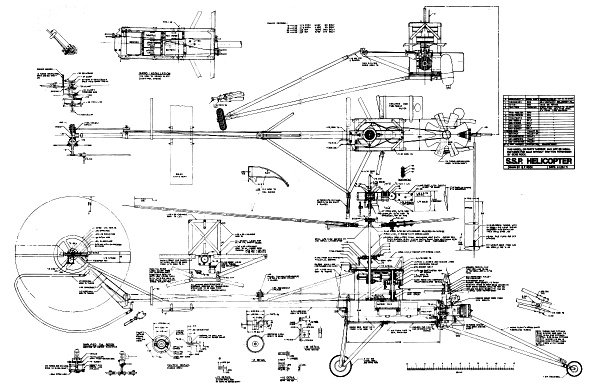
S.S.P. Helicopter Plans Sheet
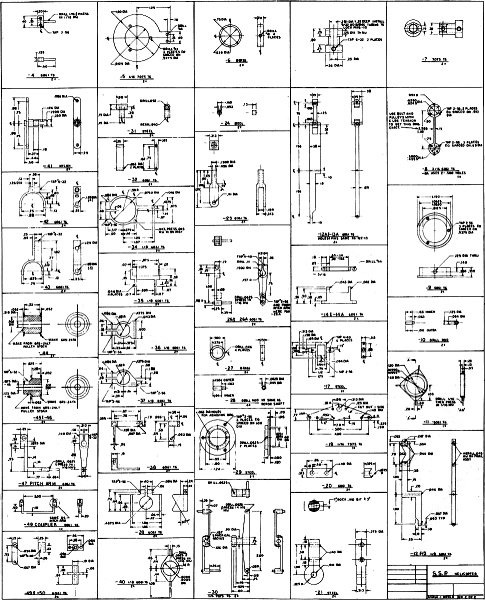
S.S.P. Helicopter Machined Parts Sheet
Notice:
The AMA Plans Service offers a
full-size version of many of the plans show here at a very reasonable cost. They
will scale the plans any size for you. It is always best to buy printed plans because
my scanner versions often have distortions that can cause parts to fit poorly. Purchasing
plans also help to support the operation of the
Academy of Model Aeronautics - the #1
advocate for model aviation throughout the world. If the AMA no longer has this
plan on file, I will be glad to send you my higher resolution version.
Try my Scale Calculator for
Model Airplane Plans.
(updated from original post on 8/28/2011)
|